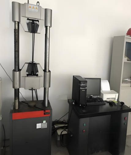
As an ISO/IEC 17025 accredited (CNAS) independent laboratory, we provide comprehensive wind load resistance evaluation for rooftop equipment, solar mounting systems, signage, lighting poles, and industrial shelters. Our test methods align with ASCE 7‑22, EN 1991‑1‑4 (Eurocode 1), GB 50009, and IEC 61215 for wind‑exposed products.

Product Samples We Regularly Test
Our wind load resistance services cover a wide range of non‑building components:
- Rooftop photovoltaic (PV) mounting systems (ballasted, penetrated, and rail‑based)
- Ground‑mounted solar trackers and fixed arrays
- Outdoor digital signage, billboards, and street furniture
- Lighting poles, traffic signal mast arms, and camera poles
- Telecommunication antennas, microwave dishes, and small cell enclosures
- Retaining walls, noise barriers, and fence systems
- Agricultural structures (greenhouses, hoop houses, windbreaks)
- Temporary event structures (tents, scaffolding, stages)
- Roof curbs, HVAC supports, and pipe bridges
- Folding arm awnings, louvered roofs, and pergolas
For Rooftop & Ground‑Mounted Solar Mounting Systems
- Static wind load test (uplift and sliding) – Per UL 2703 and IEC 62817. Apply uniform pressure via vacuum box or airbag system: positive (downward) and negative (uplift) up to 2× design wind pressure (ASCE 7‑22 exposure C). Measure rail deflection (≤ L/180), clamp slip (≤ 1 mm), and concrete block displacement for ballasted systems.
- Cyclic wind load simulation (gust fatigue) – ASTM E1592 cycle profile: 10,000 cycles from 0 to 80% design pressure at 1 Hz, then 1,000 cycles to 100% design pressure. Evaluates connection loosening, rail wear, and fatigue crack initiation in aluminum extrusions.
- Combined wind + snow load test – For regions with concurrent loading (e.g., alpine areas). Apply snow load (per ASCE 7‑22 ground snow map) then superimpose wind uplift. Pass/fail: no glass breakage in PV modules and < 0.5% permanent frame deformation.
- Wind tunnel pressure coefficient (Cp) mapping – For custom arrays, we perform scaled (1:50 to 1:100) wind tunnel tests per ASCE 49‑21 to determine actual Cp values used in structural calculations.
For Outdoor Signage, Billboards & Lighting Poles
- Static load test for sign faces and frames – According to TIA‑222‑H (telecommunication) and ASME BSR/SPRI WD‑1. Use a hydraulic actuator to apply distributed load via airbags or a grid of pull points. Measure: face deflection (≤ span/60 for aluminum faces), weld cracking, and anchor bolt elongation.
- Vibration modal analysis after wind loading – Impact hammer modal test per ISO 7626. Evaluate natural frequencies above 5 Hz to avoid resonance with vortex shedding on poles over 10 m height.
- Overturning moment test for freestanding signs – Apply horizontal line load at 1.8 m height (or centroid of sign face) incrementally until 2× design moment. Monitor foundation rotation using tiltmeters – limit < 0.5° residual tilt.
- Torque and bolt preload verification for pole flanges – Using calibrated torque wrench and ultrasonic bolt gauge, we verify installation torque meets design spec (typically 200–500 N·m for M20–M30 bolts) after 10 cycles of wind load simulation.
For Telecommunication Antennas & Small Cell Poles
- Ice + wind load combined test – Per TIA‑222‑H annex for ice‑prone regions (ice thickness 12.7 mm to 25.4 mm). Apply artificial ice coating (density 0.9 g/cm³) then perform static wind load to 1.5× design – no permanent deflection > 0.2% of height.
- Dynamic gust response (time‑history simulation) – Using multiaxial shaker table, reproduce 3‑second gust wind profile from ASCE 7‑22 (e.g., Vult = 50 m/s). Measure maximum tip displacement of antenna mast (≤ 2° tilt).
- Base shear and anchor pullout test – For rooftop small cells (4G/5G), apply horizontal shear load to 2× design base shear. Measure anchor displacement using LVDT: < 1 mm residual for post‑installed adhesive anchors per ACI 355.4.
For Agricultural & Temporary Structures
- Greenhouse frame wind load resistance – Per ISO 23488 and ASAE EP406. Apply uniform pressure to roof and sidewalls at 0.5 kPa increments up to 1.5× design (typically 0.8–1.2 kPa). Failure criterion: permanent joint opening > 3 mm or buckling of arch tubes.
- Tent and canopy tie‑down test – EN 13561 for awnings, and EN 13782 for temporary tents. Apply uplift pressure via suction fans; measure stake/pull‑out resistance in actual ground (sand, clay, or asphalt ballast). Minimum safety factor of 2.0 against overturning.
- Wind load on mesh and fabric windbreaks – Wind tunnel porosity measurement per ISO 9237 to determine pressure drop coefficient (K). Then calculate net wind load reduction (30–60% compared to solid wall).
Report Accreditation & Compliance
All wind load resistance test methods described above are performed under our ISO/IEC 17025:2017 scope (CNAS accreditation No. LXXXX). Our reports are recognized by global certification bodies: UL (Subject 2703), TÜV Rheinland (IEC 62817), Intertek (ETL for signage), and building departments referencing ASCE 7, Eurocode 1, or GB 50009. Each report includes detailed setup diagrams, instrumentation calibration records, load‑deflection curves, and a clear statement of conformity against required wind speed maps (basic wind speed Vult, Vdesign, or Vref). Solar racking manufacturers, outdoor advertising companies, telecom infrastructure owners, and structural engineers can directly use our reports for product listing, permit applications, and risk mitigation in wind‑prone zones (hurricane, typhoon, high‑wind regions).