Mechanical Time Constant Testing Service – Accredited Dynamic Response and Response Time Evaluation for Global Markets
Our internationally accredited laboratory provides a specialist mechanical time constant testing service that enables sensor manufacturers, actuator producers, relay and solenoid suppliers, motor designers and precision‑engineering companies worldwide to independently verify the dynamic response, settling time and bandwidth of their electro‑mechanical and mechanical devices. Every measurement is performed within the strict framework of ISO/IEC 17025, and each report bearing the ILAC mark is unconditionally accepted by regulatory authorities, notified bodies and supply‑chain partners in all major economies. The mechanical time constant testing service quantifies the characteristic time required for a device to reach a defined fraction of its steady‑state response following a step change in the input signal, providing the fundamental performance metric that determines the suitability of the component for closed‑loop control, high‑speed switching, vibration monitoring and precise positioning. For an exporter of servo valves, a manufacturer of vibration sensors, or a producer of high‑speed solenoids, our platform delivers the legally robust, defensible data that underpin product datasheets, customer qualification and compliance with the relevant ISO, IEC, SAE and customer‑specific standards.
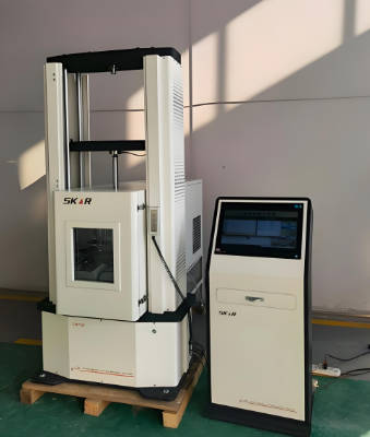
Product Samples We Regularly Subject to Mechanical Time Constant Testing
The calibrated shakers, pressure‑step generators, optical‑displacement sensors and high‑speed data‑acquisition systems in our facility accommodate devices from miniature MEMS chips to industrial actuators. The following categories represent the most frequently tested items:
- Vibration and inertial sensors – piezoelectric accelerometers, piezoresistive accelerometers, MEMS accelerometers, velocity transducers and geophones
- Pressure transducers and transmitters – piezoelectric pressure sensors, strain‑gauge pressure transducers, and miniature dynamic‑pressure probes
- Force sensors and load cells – piezoelectric force rings, strain‑gauge load cells, and impact‑force hammers
- Relays, solenoids and electro‑magnetic actuators – general‑purpose relays, reed relays, high‑speed solenoid valves, fuel‑injector solenoids and contactors
- Electric motors and servo systems – DC motors, brushless DC motors, stepper motors, voice‑coil actuators and galvo‑scanner mirrors
- Mechanical dampers and shock absorbers – hydraulic dampers, pneumatic dampers, elastomeric mounts and wire‑rope isolators
- Thermal actuators and shape‑memory‑alloy devices – wax‑motor actuators, bimetallic strips and shape‑memory‑alloy wires
Mechanical Time Constant Testing for Vibration, Pressure and Force Sensors – Step‑Response and Frequency‑Response Correlation
- Determination of the mechanical time constant of an accelerometer from the step‑response decay according to the principles of ISO 16063‑21 and ISO 5347‑15: the sensor is mounted on a rigid base, and a well‑defined mechanical step input – such as a sudden change in acceleration produced by a drop‑table, a Hopkinson bar or a rapid‑release fixture – is applied. The decaying oscillatory or exponential output signal is recorded by a high‑speed digitiser, and the time constant τ is extracted from the envelope of the decay curve. The reciprocal of the time constant gives the upper cut‑off frequency of the sensor, and the result is reported in milliseconds or microseconds. This mechanical time constant testing service provides the fundamental bandwidth data that measurement engineers use to select the correct sensor for transient‑capture applications such as crash testing, explosive‑blast monitoring and shock‑pulse measurement.
- Measurement of the time constant of pressure transducers by a shock‑tube or a fast‑acting valve: the transducer is flush‑mounted in a shock tube or a pressure‑step generator, and a step change in pressure with a rise time of a few microseconds is applied. The exponential decay of the output signal after the initial pressure step yields the mechanical time constant and the resonant frequency of the transducer–diaphragm assembly. The data are used to verify that the transducer can faithfully reproduce the cylinder‑pressure curve in an internal‑combustion engine or the blast‑wave profile in a detonation study.
- Determination of the force‑sensor time constant by an impact‑hammer or a projectile‑impact test: the sensor is struck by a calibrated impact hammer or a projectile, and the force‑time history is recorded. The decay of the ringing superimposed on the force pulse is analysed, and the mechanical time constant and the natural frequency of the force‑sensing element are extracted. This mechanical time constant testing service verifies that the force sensor will not exhibit spurious oscillations that could corrupt the measurement of the cutting force in a machining process or the thrust force in a rocket‑motor test.
- Step‑response testing of MEMS inertial sensors using an electrostatic or a piezoelectric micro‑stage: a sudden displacement or acceleration is applied to the MEMS chip, and the electrical output is sampled at mega‑samples per second. The mechanical time constant of the micro‑mechanical proof‑mass and the damping factor are extracted from the response, supporting the design optimisation of the MEMS structure and the readout electronics for automotive stability‑control, gaming and virtual‑reality applications.
- Correlation of the mechanical time constant with the frequency‑response function obtained by swept‑sine or random‑vibration excitation: the sensor is also tested on a shaker to obtain its amplitude and phase frequency‑response function. The time constant derived from the step response is compared with that calculated from the -3 dB cut‑off frequency of the frequency‑response curve. The agreement of the two methods provides the validation of the sensor model and the confidence in the reported time constant.
Mechanical Time Constant Testing for Relays, Solenoids and Electro‑Magnetic Actuators – Operate and Release Dynamics
- Measurement of the operate time, release time and mechanical time constant of electromechanical relays according to IEC 61810‑7 and the relevant customer specifications: the coil is energised with a step‑change voltage, and the movement of the armature or the closure of the contacts is detected by a high‑speed optical sensor or by the voltage drop across the contacts. The operate time, the bounce time and the release time are recorded. The mechanical time constant is derived from the exponential build‑up or decay of the armature displacement, and the data are reported in milliseconds. This mechanical time constant testing service provides the essential switching‑speed parameters that circuit designers require for the timing‑critical control of motors, heaters and safety‑interlock systems.
- Dynamic characterisation of solenoid valves and fuel‑injector solenoids according to the automotive OEM standards: the solenoid is driven by a current pulse that simulates the engine‑control‑unit output, and the displacement of the plunger or the needle is measured by a laser vibrometer or an eddy‑current sensor. The opening time, the closing time and the mechanical time constant of the plunger motion are reported, directly supporting the calibration of the injector‑model in the engine‑management software and the assurance of consistent fuel‑delivery across the production batch.
- Testing of high‑speed pneumatic and hydraulic servo valves: a step change in the command voltage is applied to the valve, and the spool position or the output flow rate is recorded. The mechanical time constant of the spool displacement is extracted from the exponential approach to the steady‑state position, and the data are used to specify the valve for closed‑loop position‑control, force‑control or vibration‑testing applications where a fast response is critical.
- Characterisation of contactors and large‑current relays for electric‑vehicle and energy‑storage applications: the mechanical time constant is measured under the rated coil voltage and at elevated temperatures, and the effect of the contact‑gap wear, the spring‑force relaxation and the armature‑mass on the response time is evaluated. The test ensures that the contactor will open and close within the time limits required for the safe disconnection of the traction battery under fault conditions.
- Determination of the mechanical time constant of voice‑coil actuators and optical‑scanning galvanometers: the actuator is driven by a step‑current command, and the angular or linear displacement is measured by a position‑sensitive detector or an interferometer. The time to reach 63.2 % of the final position – the mechanical time constant – and the settling time to within ±1 % of the final position are reported, providing the data that laser‑system integrators use to set the maximum scan rate and to avoid image distortion in confocal microscopy, LIDAR and laser‑marking applications.
Mechanical Time Constant Testing for Motors, Dampers and Thermal Actuators – Rotor Inertia, Damping and Heating Dynamics
- Determination of the mechanical time constant of DC and brushless‑DC motors from the speed‑versus‑time curve during a step‑voltage start: the motor is coupled to a known inertial load, and the shaft speed is measured by an optical encoder or a tachogenerator. The speed‑time curve is recorded, and the mechanical time constant τm – the time for the motor to reach 63.2 % of the no‑load speed – is calculated from the slope of the tangent at the origin or by a curve‑fit to the exponential model. This mechanical time constant testing service provides the data that motion‑control engineers use to tune the PID controller gains, to select the correct gear ratio and to predict the acceleration performance of the axis.
- Measurement of the mechanical time constant of stepper motors and the resonance‑suppression damping: the motor is excited by a step‑pulse command, and the angular oscillation of the rotor about the equilibrium position is recorded. The mechanical time constant of the decay envelope and the natural frequency of the rotor–stator system are reported, enabling the selection of the appropriate micro‑stepping, current‑decay mode or external damper to suppress the ringing and to ensure accurate positioning.
- Characterisation of the mechanical time constant of hydraulic and pneumatic dampers by a drop‑test or a force‑step test: a mass is dropped onto the damper or a rapid‑release mechanism applies a step force, and the displacement‑time curve is recorded. The time constant of the exponential approach to the equilibrium position yields the damping coefficient and the mechanical time constant of the damper, which are used by vehicle‑suspension designers to predict the ride‑comfort and handling characteristics.
- Testing of wax‑motor and shape‑memory‑alloy thermal actuators: the actuator is heated by a step change in the electrical current or the fluid temperature, and the displacement is recorded by a linear‑variable‑differential transformer or a laser displacement sensor. The mechanical time constant of the thermal expansion or the shape‑memory phase‑transformation is reported, and the data are used to design the temperature‑control loop and to guarantee the response time for the thermostatic valve, the automotive‑climate‑control flap or the fire‑sprinkler release mechanism.
- Determination of the mechanical time constant of shock absorbers and elastomeric mounts by the rebound‑test method: the mount is compressed or extended to a defined preload, and the load is suddenly released. The damped oscillation of the mass supported by the mount is recorded by an accelerometer, and the logarithmic decrement and the mechanical time constant are calculated, providing the parameters that civil and mechanical engineers use to predict the vibration‑isolation performance of the mount under seismic or traffic‑induced excitation.
Report Acceptance and Global Regulatory Compliance
All measurements performed within our mechanical time constant testing service are executed under the fully accredited scope of our ISO/IEC 17025 quality management system. Each test report that carries the ILAC mark is therefore automatically recognised by regulatory authorities, notified bodies, customs offices and supply‑chain partners in all major economies. For sensor manufacturers, actuator producers, relay and solenoid suppliers, motor designers and precision‑engineering companies anywhere in the world, the report constitutes legally robust, internationally accepted evidence that the mechanical time constant, the response time and the dynamic behaviour of the device have been determined in accordance with the applicable ISO, IEC, SAE and customer‑specified methods. The documentation can be directly used to support CE marking, the issue of inspection certificates according to EN 10204 or equivalent national standards, the compilation of technical files for type‑examination, and the resolution of commercial and technical disputes concerning the dynamic response and the operating speed of electro‑mechanical and mechanical components.