Mechanical and Thermal Cycling Testing Services – Accredited Combined Mechanical Evaluation and Thermal Endurance for Global Markets
Our internationally accredited laboratory delivers a comprehensive suite of mechanical experiments and thermal cycling experiments that can be performed independently or in a seamlessly combined programme to give manufacturers of automotive components, electronic assemblies, aerospace structures, medical devices and industrial machinery worldwide the complete picture of how their products behave under load, under temperature extremes and under the superimposed action of both. Every test is conducted within the rigorous framework of ISO/IEC 17025, and each report bearing the ILAC mark is unconditionally accepted by regulatory authorities, notified bodies and supply‑chain partners in all major economies. The mechanical experiments – tensile, compression, bending, shear, impact and fatigue – quantify the strength, stiffness, ductility and energy‑absorption capacity of a material or a component at room temperature, at elevated temperature or at cryogenic conditions. The thermal cycling experiments expose the same product to precisely controlled, repeated alternations between a high‑temperature and a low‑temperature extreme, reproducing the thermomechanical fatigue that accumulates in solder joints, encapsulations, seals and material interfaces over years of service. When the two programmes are combined into a single mechanical and thermal cycling experiment, the specimen is mechanically loaded while it is being thermally cycled, or its residual mechanical properties are measured after a defined number of thermal cycles, providing the design engineer with the most realistic, legally robust data on the product's durability, reliability and safe operating envelope.
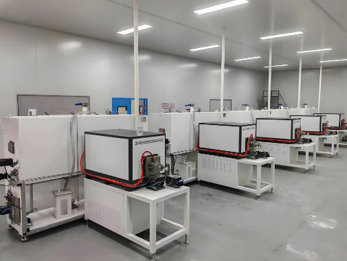
Product Samples We Regularly Subject to Mechanical and Thermal Cycling Experiments
Our servo‑hydraulic test frames, thermal cycling chambers, extensometers, digital‑image‑correlation systems and high‑speed data‑acquisition units accommodate a vast variety of materials, sub‑assemblies and finished products. The following categories represent the items most frequently evaluated through our mechanical experiments and thermal cycling experiments:
- Electronic assemblies and printed‑circuit‑board modules – ball‑grid‑array packages, surface‑mount resistors and capacitors, soldered interconnects, conformally coated boards, engine control units, transmission controllers and battery‑management systems
- Automotive mechatronic and structural components – engine‑mounted sensors and actuators, ABS hydraulic blocks, electric‑power‑steering controllers, on‑board chargers, brake calipers, suspension springs and anti‑roll bars
- Aerospace and defence articles – turbine‑blade alloys, landing‑gear forgings, satellite‑electronic enclosures, radome‑support structures and missile‑guidance‑section housings
- Medical devices and implantable components – orthopaedic screws and plates, spinal‑fixation rods, dental‑implant abutments, surgical‑instrument handles and sterilizable electronic monitors
- LED lighting and optical systems – headlamp LED modules, street‑lantern light engines, aviation‑obstruction lights and outdoor‑display panels
- Batteries and energy‑storage systems – lithium‑ion cells, battery modules, supercapacitors and the structural frames of stationary storage racks
- Seals, gaskets and encapsulated assemblies – elastomeric O‑rings, flat gaskets, cable glands, overmoulded connectors and sealed enclosures with IP67 or higher ratings
- Plastics, composites and structural adhesives – glass‑fibre‑reinforced brackets, carbon‑fibre panels, bonded aluminium‑composite joints, potting compounds and multi‑layer laminates
Mechanical Experiments – Tensile, Compression, Bending, Shear, Impact and Fatigue Testing According to ISO, ASTM and EN Standards
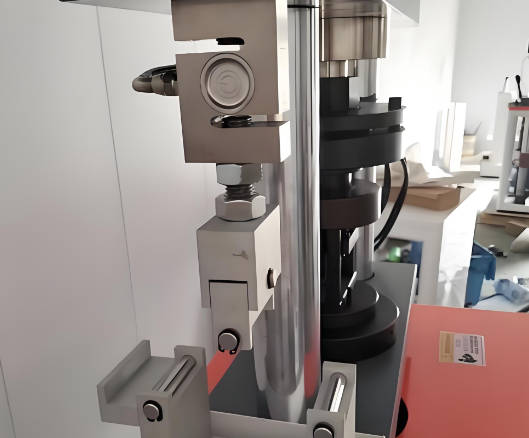
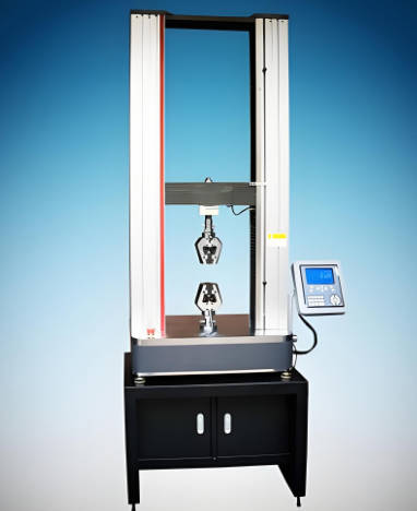
- Uniaxial tensile and compression testing at room, elevated and cryogenic temperatures according to ISO 6892‑1, ASTM E8, ISO 6892‑2 and ASTM E9: the specimen is machined to a standardised geometry and loaded to failure under a controlled strain rate. The yield and the ultimate strength, the elongation at fracture, the reduction of area and the full stress‑strain curve are reported. These mechanical experiments provide the fundamental data for material selection, quality assurance and the certification of structural and pressure‑bearing components.
- Three‑point and four‑point bending, flexural and shear testing of metals, plastics, composites and ceramics according to ISO 178, ASTM D790, ASTM D2344 and ISO 7438: the specimen is supported on two rollers and loaded at mid‑span or at two points, and the flexural strength, the flexural modulus, the deflection at break and the interlaminar shear strength are reported, supporting the design of beams, panels and laminated structures.
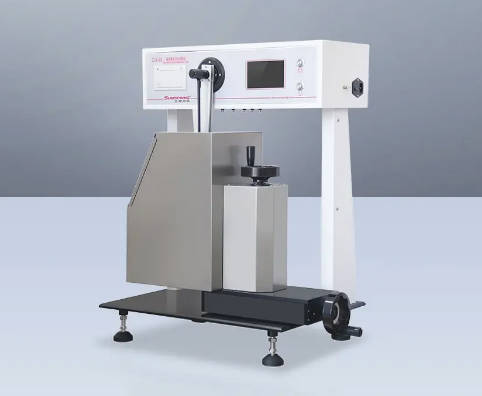
- Instrumented Charpy and Izod impact testing, and drop‑weight tear testing according to ISO 148‑1, ASTM E23 and ASTM E436: the energy absorbed during the fracture of a notched or a pre‑cracked specimen is measured at the room temperature and at the sub‑zero temperatures, providing the toughness and the ductile‑to‑brittle transition data that are essential for the safety assessment of welded and structural components.
- High‑cycle and low‑cycle fatigue testing according to ISO 1099, ASTM E466 and ASTM E606: the specimen is subjected to a sinusoidal or a service‑spectrum cyclic load, and the S‑N curve, the fatigue limit and the crack‑initiation life are determined. The test may be performed under the load‑control or the strain‑control mode, and it generates the endurance data that the engineer uses to set the inspection and the replacement intervals for the dynamic components.
- Creep and stress‑rupture testing at the elevated temperature according to ISO 204 and ASTM E139: a constant tensile or compressive load is applied to the specimen at a controlled high temperature for up to 10 000 hours, and the creep‑strain curve and the time to rupture are recorded, providing the long‑term design data for the power‑plant, the turbine and the pressure‑vessel components.
Thermal Cycling Experiments – Temperature Shock, Rapid Thermal Cycling and Combined Environmental Stresses According to IEC 60068‑2‑14 and ISO 16750‑4
- Test Na – rapid temperature change with a prescribed transfer time according to ČSN EN 60068‑2‑14 (IEC 60068‑2‑14): the specimen is transferred between a hot chamber at +100 °C to +150 °C and a cold chamber at -40 °C to -65 °C within a few seconds, and the dwell time at each extreme is at least 10 minutes. Between 100 and 1 000 cycles are applied. These thermal cycling experiments subject the solder joints, the plated through‑holes, the encapsulations and the seals to the maximum thermomechanical stress, and the electrical continuity, the hermeticity and the visual integrity are monitored throughout.
- Test Nb – temperature change with a specified rate of change according to ČSN EN 60068‑2‑14: a single‑chamber method applies a ramp rate of 3 °C/min, 5 °C/min or 10 °C/min between -55 °C and +125 °C for 200 to 500 cycles. The test is suited to the large, high‑thermal‑mass assemblies where the internal temperature gradient governs the stress on the conformal coatings, the ceramic capacitors and the large‑area interfaces.
- Combined temperature and humidity cycling according to the automotive and the railway standards, including ISO 16750‑4 and EN 50155: a 24‑hour cycle alternates between the sub‑zero temperature and the warm, humid phase at 85 % relative humidity, simulating the condensation and the drying that occur in the passenger compartment, the under‑bonnet environment and the outdoor trackside equipment.
- Thermal cycling of the battery packs and the energy‑storage modules according to UN 38.3, IEC 62133‑2 and IEC 62619: the cells and the packs are cycled between the upper and the lower temperature limits, and the capacity loss, the impedance rise and the integrity of the safety vent are evaluated, providing the safety and the lifetime data for the transport and the stationary storage applications.
- Thermal cycling of the sealed enclosures and the cable glands according to ČSN EN 60529 and the internal procedures: an IP66 or IP67 enclosure with its gaskets and the cable entries is cycled between -25 °C and +55 °C, and the dust and the water‑jet tests are performed after the cycling, verifying that the gasket compression set and the plastic‑housing dimensional change have not created a leak path.
Combined Mechanical and Thermal Cycling Experiments – The Synergistic Evaluation of Load and Temperature Cycling
- Residual mechanical properties after a defined number of thermal cycles: the specimen is first subjected to a prescribed thermal‑cycling programme, and then the tensile, the bending or the impact test is performed at the room temperature. The percentage retention of the strength, the modulus and the elongation is reported, quantifying the thermal‑fatigue‑induced degradation of the material. This mechanical and thermal cycling experiment is the industry‑standard method for the qualification of the engine‑compartment plastics, the solder‑joint reliability and the composite‑laminate durability.
- In‑situ mechanical loading during the thermal cycling – the thermomechanical fatigue test: the specimen is mounted in a servo‑hydraulic test frame inside a thermal chamber, and a cyclic mechanical load is applied simultaneously with the temperature cycles. The phase relationship between the mechanical and the thermal strains – in‑phase or out‑of‑phase – is controlled, and the number of cycles to the crack initiation and to the final fracture is recorded. The test reproduces the most aggressive service conditions experienced by the turbine blades, the exhaust‑manifold gaskets and the power‑electronics substrates, and it generates the Coffin‑Manson and the life‑prediction curves.
- Combined vibration, thermal cycling and mechanical‑load endurance for the automotive and the aerospace electronic units: the device is mounted on a shaker table inside a thermal chamber, and a random or a swept‑sine vibration profile is applied while the temperature is cycled and the device is electrically powered. The functional parameters are continuously monitored, and the test identifies the intermittent contact failures, the solder‑crack propagation and the bond‑wire lift‑off that are caused by the synergistic action of the vibration and the thermal stress.
- Mechanical creep and the stress‑relaxation measurement during the thermal cycling: a constant tensile or compressive load is applied to the specimen, and the temperature is cycled while the deformation is recorded. The thermal‑cycling‑enhanced creep rate and the relaxation‑induced loss of the preload are quantified, providing the data that the joint designer uses to specify the correct tightening torque and the seal‑groove depth for the components that experience the daily or the seasonal temperature swings.
- Post‑thermal‑cycling burst, proof‑pressure and leak testing of the pressure‑containing components: after the thermal cycling, the component is pressurised to the rated proof‑pressure or to the burst, and the leakage rate, the deformation and the failure mode are evaluated. This mechanical and thermal cycling experiment verifies that the pressure‑vessel, the hose, the valve or the expansion joint retains its structural integrity and its seal function after the repeated thermal expansion and contraction.
Report Acceptance and Global Regulatory Compliance
All mechanical experiments and thermal cycling experiments described above are executed under the fully accredited scope of our ISO/IEC 17025 quality management system. Each test report that carries the ILAC mark is therefore automatically recognised by regulatory authorities, notified bodies, customs offices and supply‑chain partners in all major economies. For automotive tier‑one suppliers, aerospace component manufacturers, electronics producers, medical‑device developers and industrial equipment builders anywhere in the world, the report constitutes legally robust, internationally accepted evidence that the mechanical strength, the thermal‑cycling endurance and the synergistic thermomechanical durability of the product have been determined in accordance with the applicable ISO, ASTM, IEC, EN and customer‑specified methods. The documentation can be directly used to support CE marking, to issue inspection certificates according to EN 10204 or equivalent national standards, to compile the technical file for type‑examination, and to resolve commercial and technical disputes concerning the long‑term reliability and the safe service life of any product subjected to combined mechanical and thermal loads.