Contact Resistance Measurement Experiment – Accredited Electrical Interface Reliability Testing for Global Markets
Our internationally accredited laboratory provides a specialist contact resistance measurement experiment service that supplies manufacturers of connectors, relays, switches, busbars, printed‑circuit‑board contacts and electronic components worldwide with the precise, traceable data they need to evaluate the integrity, stability and long‑term performance of their electrical interfaces. Every test is conducted under the rigorous framework of ISO/IEC 17025, and each report bearing the ILAC mark is unconditionally accepted by regulatory authorities, notified bodies and supply‑chain partners in all major economies. The measurement experiment of contact resistance of contacts quantifies the opposition to current flow at the mating surfaces using four‑terminal Kelvin methods, dry‑circuit techniques and dynamic load‑cycling approaches, providing the critical quality metrics that design engineers use to ensure low power loss, signal integrity and freedom from thermal runaway in connectors, switching devices and electrical joints. By performing these measurements under controlled environmental conditions, after mechanical endurance tests and following exposure to corrosive atmospheres, we deliver the legally robust, defensible data that underpin product qualification, warranty validation and compliance with the relevant IEC, ASTM, EN and customer‑specified standards.
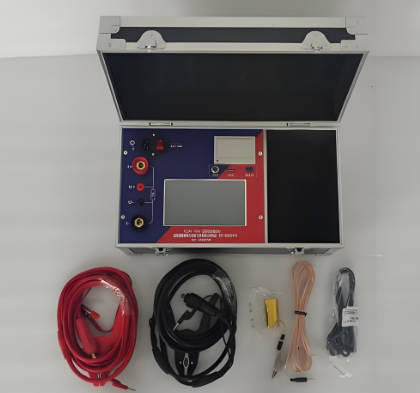
Product Samples We Regularly Subject to Contact Resistance Measurement Experiments
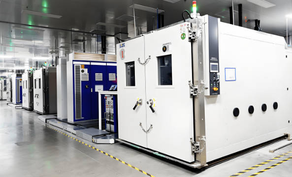
Our precision micro‑ohmmeters, dry‑circuit testers, environmental chambers and contact‑cycling rigs accommodate a vast array of electromechanical components. The following categories represent the most frequently tested items:
- Connectors and interconnects – circular, rectangular, D‑subminiature, coaxial and fibre‑optic‑connector electrical contacts for aerospace, automotive, industrial and data‑communication applications
- Terminal blocks and binding posts – screw‑type, spring‑cage, insulation‑displacement and push‑in connectors for building wiring, control cabinets and power distribution
- Relays and contactors – electromechanical, reed and solid‑state relay output contacts, and the main and auxiliary contacts of industrial contactors and motor starters
- Switches and keyboards – toggle, push‑button, slide, rotary and membrane switch contacts, including the dome‑array contacts of computer keyboards and control panels
- Busbars and bolted electrical joints – aluminium and copper busbar splice plates, bolted‑lug terminations, and the contact interfaces in switchgear, panel‑boards and distribution cabinets
- Battery and power‑storage connectors – blade‑type, bolted and quick‑connect terminals on lithium‑ion battery packs, uninterruptible‑power‑supply modules and electric‑vehicle charging connectors
- Sliding contacts and commutators – brush‑commutator interfaces in motors and generators, slip‑ring assemblies and potentiometer wiper contacts
- Plated and coated test coupons – flat‑on‑flat gold, silver, tin and palladium‑nickel plated specimens for the evaluation of the intrinsic contact‑resistance behaviour of the surface finish
Low‑Voltage Connectors, Contacts and Terminal Blocks – Contact Resistance Measurement According to IEC 60512‑2 and ASTM B539
- Millivolt‑drop and four‑wire resistance measurement according to IEC 60512‑2 (Connectors for electronic equipment – Tests and measurements – Contact resistance) and ASTM B539 (Standard Test Methods for Measuring Contact Resistance of Electrical Connections): a specified direct current, typically 100 mA for signal contacts and up to 10 A for power contacts, is passed through the mated connector pair, and the voltage drop is measured by a four‑terminal Kelvin method using a high‑precision micro‑ohmmeter. The contact resistance in milliohms is calculated, and the result is compared with the maximum‑allowed value for the connector type. This contact resistance measurement experiment is the fundamental acceptance test for every production batch of connectors, relay sockets and terminal blocks destined for the automotive, industrial and consumer‑electronics sectors.
- Low‑level contact resistance (dry‑circuit) testing according to the principles of ASTM B539 and MIL‑STD‑202 Method 307: the measurement is performed with an open‑circuit voltage not exceeding 20 mV and a short‑circuit current not exceeding 100 mA to avoid the electrical breakdown of any surface film. The test reveals the true constriction resistance of the a‑spots and is mandatory for the qualification of gold‑plated signal contacts, reed‑relay switches and high‑reliability aerospace connectors.
- Contact‑resistance measurement after the mechanical endurance and the insertion‑and‑withdrawal cycling: the connector pair is subjected to a defined number of mating cycles – typically 500, 1 000 or 5 000 – and the contact resistance is measured at intervals. The increase in the resistance and the number of cycles to reach a critical threshold are reported, providing the data that the design engineer uses to specify the connector durability and the maintenance interval.
- Influence of the contact force, the wipe distance and the geometry on the contact resistance: the normal force is varied by a micro‑positioner, and the contact resistance is measured as a function of the load. The measurement experiment of contact resistance of contacts determines the minimum contact force required to achieve the stable, low‑resistance interface, and the data are used to set the spring‑design parameters for the contact clip or the socket.
- Dynamic contact‑resistance measurement during the vibration and the mechanical shock: the mated connector is mounted on a shaker table, and the contact resistance is continuously monitored during the exposure to the random or the swept‑sine vibration profile. The test detects any momentary increase in the resistance – the so‑called “fretting” or “micro‑interruption” – that could corrupt a digital signal or a safety‑critical sensor reading.
High‑Current Contacts, Busbars and Circuit Breakers – Contact Resistance Measurement According to IEC 62271‑1 and ASTM B539
- Determination of the contact resistance of the main‑current‑carrying contacts of a circuit breaker, a disconnector or a busbar joint according to IEC 62271‑1 (High‑voltage switchgear and controlgear) and the relevant clauses of IEEE C37.09: a direct current of at least 100 A, or the rated normal current, is passed through the closed contacts, and the voltage drop across the contact interface is measured by a calibrated milli‑voltmeter. The contact resistance is reported in micro‑ohms, and the value must be below the limit specified by the manufacturer for the particular type and the current rating of the device. This contact resistance measurement experiment is the routine field‑diagnostic test for the condition assessment of the high‑voltage and the medium‑voltage switchgear contacts.
- Contact‑resistance mapping of the multi‑finger and the tulip‑type high‑current contacts: the resistance is measured individually on each contact finger or on each segment of the contact assembly, and the non‑uniformity is reported. The test identifies the poorly contacting fingers that will overheat and cause a thermal runaway during the short‑circuit or the overload condition.
- Thermal‑transient contact‑resistance measurement during the rated‑current and the overload‑current cycling: the contact is heated by the current, and the resistance is measured at the elevated temperature as well as after the cooling. The thermal‑runaway behaviour and the hysteresis of the resistance versus the temperature are reported, and the data are used to set the maximum‑permissible continuous current for the connector or the busbar joint.
- Contact‑resistance measurement after the short‑circuit and the fault‑current exposure: the contact is subjected to a defined peak‑withstand current, and the resistance is measured before and after the event. Any permanent increase in the resistance indicates the melting, the welding or the plastic deformation of the contact spots, and the test supports the qualification of the device for the specified fault‑current rating.
- In‑situ contact‑resistance monitoring of the bolted and the compression electrical joints using the micro‑ohmmeter and the infrared‑thermography correlation: the joint is tightened to the design torque, and the contact resistance is measured and correlated with the temperature rise measured by the infrared camera. The measurement experiment of contact resistance of contacts establishes the acceptance criterion for the joint resistance and the tightening procedure.
Relays, Switches and Sliding Contacts – Dynamic Contact Resistance and Low‑Level Contact Reliability
- Contact‑resistance measurement of the relay and the switch contacts according to the principles of IEC 61810‑7 and the relevant automotive OEM standards: the contact is operated at the rated voltage and the rated current, and the contact resistance is measured immediately after the closure and just before the opening by a high‑speed digitiser. The dynamic contact‑resistance profile, the bounce time and the resistance during the bounce are reported. This contact resistance measurement experiment is essential for the qualification of the relay for the critical‑safety functions such as the air‑bag deployment, the anti‑lock braking and the railway signalling.
- Low‑level contact‑resistance testing of the reed‑relay, the micro‑switch and the sealed‑switch contacts for the dry‑circuit and the wetting‑current characterisation: the test is performed at the millivolt and the milliampere level to simulate the operation in the thermocouple‑input and the audio‑signal circuits. The resistance, the noise and the thermal‑EMF of the contact are reported, and the minimum wetting current is determined.
- Contact‑resistance evolution of the sliding and the brush contacts during the accelerated wear and the spark‑erosion testing: a commutator‑and‑brush or a slip‑ring‑and‑brush assembly is rotated at a controlled speed and current, and the contact resistance is continuously logged. The test maps the resistance noise, the arc‑erosion rate and the brush‑wear debris effect, providing the life‑prediction data for the motor and the generator brushes.
- Measurement of the contact‑resistance hysteresis and the stick‑slip behaviour of the potentiometer and the encoder contacts: the wiper is moved across the resistive track at a constant speed, and the contact resistance is sampled at a high rate. The deviation, the drop‑out and the short‑term variation are reported, and the data are used to guarantee the smooth, noise‑free output of the position‑sensing device.
Plated, Coated and Aged Contact Surfaces – Correlation of Contact Resistance with Environmental Degradation
- Contact‑resistance measurement after the exposure to the neutral‑salt‑spray, the mixed‑flowing‑gas and the industrial‑atmosphere corrosion tests according to IEC 60068‑2‑11 and ASTM B845: the connector or the test coupon is exposed to the corrosive atmosphere for a defined period, and the contact resistance is measured after the exposure and after a controlled number of the mating cycles. The increase in the resistance and the number of the cycles required to restore the low‑resistance condition are reported, providing the data that the plating‑system developer uses to compare the corrosion‑resistance of the gold, the palladium‑nickel, the silver and the tin finishes.
- In‑situ contact‑resistance monitoring during the fretting‑corrosion and the micro‑motion testing: a micro‑positioner applies a reciprocating tangential motion of a few micrometres to the contact interface while the contact resistance is continuously recorded. The measurement experiment of contact resistance of contacts captures the instantaneous resistance spikes caused by the oxide‑wear‑debris build‑up, and the data are used to qualify the contact lubricants and the coating systems for the automotive and the vibration‑prone applications.
- Contact‑resistance measurement as a function of the thermal ageing and the intermetallic‑compound growth: the soldered or the press‑fit contact interface is aged at the elevated temperature, and the contact resistance and the cross‑sectional microscopy are performed at intervals. The experiment establishes the maximum‑permissible ageing time and the temperature that can be tolerated before the contact resistance exceeds the design limit.
- Evaluation of the contact‑resistance recovery after the contact‑cleaning and the de‑oxidising treatments: the oxidized or the sulphidised contact is treated with the cleaning solvent, the abrasive pad or the chemical de‑oxidiser, and the contact resistance is remeasured. The test determines the most effective field‑maintenance procedure for the tarnished connectors in the telecommunications and the power‑distribution systems.
Report Acceptance and Global Regulatory Compliance
All measurements performed within our contact resistance measurement experiment service are executed under the fully accredited scope of our ISO/IEC 17025 quality management system. Each test report that carries the ILAC mark is therefore automatically recognised by regulatory authorities, notified bodies, customs offices and supply‑chain partners in all major economies. For connector manufacturers, switchgear producers, relay and contactor suppliers and electrical‑joint designers anywhere in the world, the report constitutes legally robust, internationally accepted evidence that the contact resistance, the low‑level behaviour and the environmental stability of the electrical interface have been determined in accordance with the applicable IEC, ASTM, EN and customer‑specified methods. The documentation can be directly used to support CE marking, the issue of inspection certificates according to EN 10204 or equivalent national standards, the compilation of the technical file for the type‑examination, and the resolution of commercial and technical disputes concerning the electrical‑contact reliability and the long‑term performance of any electromechanical component.