Light Absorption Loss Testing Service – Accredited Optical Attenuation and Absorption Measurement for Global Markets
Our internationally accredited laboratory delivers a specialist light absorption loss testing service that provides fibre‑optic cable manufacturers, optical‑component producers, laser‑system integrators, photovoltaic‑module developers, coating formulators and research institutes worldwide with the independent, traceable data they need to quantify the attenuation, absorption and optical loss of their materials and devices. Every measurement is performed within the rigorous framework of ISO/IEC 17025, and each report bearing the ILAC mark is unconditionally accepted by regulatory authorities, notified bodies and supply‑chain partners in all major economies. The light absorption loss testing service employs spectrophotometry, integrating‑sphere reflectance, laser calorimetry, cavity‑ring‑down spectroscopy and optical‑time‑domain reflectometry to measure the spectral absorption coefficient, the extinction ratio, the attenuation per unit length and the total optical loss across the ultraviolet, visible and infrared regions. For an exporter of single‑mode fibres, a developer of anti‑reflective coatings, or a manufacturer of high‑power laser optics, our platform provides the legally robust, defensible data that underpin product certification, performance‑guarantee validation and compliance with the relevant IEC, ISO, ASTM and ITU‑T standards.
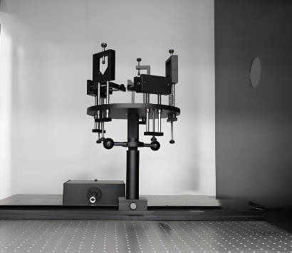
Product Samples We Regularly Subject to Light Absorption Loss Testing
The precision photometric, interferometric and fibre‑optic test benches in our facility accommodate bulk optics, fibre coils and thin‑film coupons. The following categories represent the materials and components most frequently analysed through our light absorption loss testing service:
- Optical fibres and cables – single‑mode and multi‑mode telecommunications fibres, erbium‑doped and ytterbium‑doped amplifier fibres, photonic‑crystal fibres, polymer optical fibres, and fibre‑optic cables for submarine, terrestrial and premises networks
- Thin films, coatings and optical surfaces – anti‑reflective coatings, high‑reflection dielectric mirrors, beam‑splitter coatings, transparent conductive oxides, solar‑control films and photoresist layers on glass or semiconductor substrates
- Solar cells and photovoltaic materials – crystalline‑silicon wafers, thin‑film CIGS and CdTe modules, perovskite solar‑cell test coupons, multi‑junction III‑V cells, and encapsulated mini‑modules
- Laser crystals, glasses and gain media – Nd:YAG, Yb:YAG, Ti:sapphire and Cr:LiSAF crystals, neodymium‑doped phosphate and silicate glasses, and ceramic laser gain media
- Filters, lenses and bulk optical components – coloured‑glass and interference filters, polarising beam splitters, gradient‑index lenses, prisms, cuvettes and windows for high‑power or ultraviolet applications
- Liquids, gels and biological media – laser‑dye solutions, optical‑immersion oils, tissue‑simulating phantoms, cell‑culture media and nanoparticle suspensions for biomedical optics
Light Absorption Loss Testing Service for Optical Fibres and Waveguides – Attenuation, Cut‑Off and Backscatter
- Spectral attenuation measurement of optical fibres by the cut‑back method according to IEC 60793‑1‑40 (Optical fibres – Part 1‑40: Measurement methods – Attenuation) and ITU‑T G.650.1: a broadband light source or a tuneable laser is launched into a full‑length fibre, and the transmitted power is recorded. The fibre is then cut back to a reference length of typically 2 m, and the power at the reference length is measured. The spectral attenuation coefficient in dB/km is calculated as a function of wavelength, and the attenuation at the water‑peak, the C‑band and the L‑band is reported. This light absorption loss testing service provides the fundamental loss data that fibre manufacturers use to certify their products to the ITU‑T G.652, G.655 and G.657 recommendations.
- Optical‑time‑domain reflectometry for distributed loss and event‑loss measurement according to IEC 60793‑1‑40 Annex B and IEC 61746: an OTDR launches a pulse into the fibre and records the Rayleigh‑backscattered signal as a function of time, yielding the one‑way attenuation profile along the entire length. The splice loss, connector loss, macro‑bend loss and the attenuation uniformity are reported, and the data are used for the installation‑certification of long‑haul and fibre‑to‑the‑home links.
- Macro‑bend and micro‑bend loss measurement according to IEC 60793‑1‑47 and IEC 60793‑1‑40: the fibre is wound on a mandrel of a specified diameter – typically 10 mm, 15 mm or 30 mm – and the increase in the attenuation at 1625 nm or 1550 nm is recorded. The test verifies that the fibre meets the bend‑insensitive specifications required for dense‑access and indoor installations.
- Water‑peak attenuation and hydrogen‑ageing loss according to IEC 60793‑2‑50 Annex E and the relevant ITU‑T recommendations: the fibre is exposed to a hydrogen‑rich atmosphere at an elevated temperature, and the growth of the OH‑ion absorption peak at 1383 nm is measured. The test quantifies the long‑term hydrogen‑induced loss and is mandatory for fibres destined for submarine and oil‑and‑gas applications.
- Spectral absorption‑loss characterisation of doped amplifier fibres by the cut‑back method with a tuneable laser and an integrating sphere: the absorption coefficient at the pump wavelength and the gain‑band absorption are measured, and the data are used to model the amplifier performance and to optimise the fibre length in erbium‑doped‑fibre amplifiers.
Light Absorption Loss Testing Service for Thin Films, Coatings and Optical Materials – Spectrophotometry, Cavity‑Ring‑Down and Laser Calorimetry
- Determination of the spectral transmittance, reflectance and absorptance of thin films and bulk materials according to ISO 15368 (Optics and photonics – Measurement of reflectance and transmittance) and ASTM E903 (Standard Test Method for Solar Absorptance, Reflectance and Transmittance of Materials Using Integrating Spheres): the sample is illuminated with a monochromatic beam, and the total hemispherical transmittance and reflectance are measured using an integrating‑sphere spectrophotometer. The absorptance is calculated as 1 minus the transmittance minus the reflectance, and the absorption coefficient is derived from the sample thickness. This light absorption loss testing service provides the complete optical‑loss budget for anti‑reflective coatings, solar‑control films and low‑emissivity glazing.
- Cavity‑ring‑down spectroscopy for ultra‑low absorption measurement of high‑reflectance coatings and bulk optics according to ISO 13695 (Optics and photonics – Lasers and laser‑related equipment – Test methods for the spectral characteristics of lasers) and the relevant laser‑industry standards: a laser pulse is injected into a high‑finesse optical cavity formed by two mirrors, one of which is the test optic, and the exponential decay time of the light leaking from the cavity is recorded. The absorption‑loss coefficient of the coating or the substrate is extracted from the ring‑down time with a sensitivity better than 1 ppm, enabling the qualification of mirrors for gravitational‑wave detectors, ring‑laser gyroscopes and extreme‑ultraviolet lithography.
- Laser calorimetry for the direct measurement of the absorption coefficient of transmissive optics according to ISO 11551 (Optics and photonics – Lasers and laser‑related equipment – Test method for absorptance of optical laser components): the sample is irradiated with a high‑power laser beam, and the temperature rise of the sample is measured by a thermocouple or an infrared camera. The absorption coefficient in cm⁻¹ is calculated from the thermal‑relaxation curve, and the data are used to specify the laser‑induced‑damage threshold and to select the bulk material for high‑energy laser windows and lenses.
- Photothermal common‑path interferometry for absorption‑mapping of coated surfaces: a pump laser heats the sample locally, and the resulting thermal‑lens effect or surface deformation is detected by a probe laser. The absorption map with a spatial resolution of a few micrometres reveals the uniformity of the coating and the presence of any absorbing defects, providing the quality‑control feedback that coating houses use to refine their deposition process.
- Measurement of the absorption edge and the Urbach tail of optical glasses and crystals: the transmittance is recorded at a very fine wavelength step around the band‑gap energy, and the absorption‑edge wavelength and the Urbach energy are reported. The data are used to classify the glass type and to predict the transmission performance in the ultraviolet and infrared spectral regions.
Light Absorption Loss Testing Service for Solar Cells and Photovoltaic Materials – Quantum Efficiency and Parasitic Absorption
- Determination of the external quantum efficiency and the internal quantum efficiency of solar cells according to IEC 60904‑8 (Photovoltaic devices – Part 8: Measurement of spectral responsivity of a photovoltaic device): the cell is illuminated with a monochromatic beam, and the photocurrent is measured as a function of wavelength. The external quantum efficiency – the ratio of collected electrons to incident photons – is reported, and the internal quantum efficiency is derived by correcting for the reflectance. The parasitic absorption losses in the window layer, the buffer layer and the back‑contact are identified, providing the data that cell developers use to optimise the layer stack and the anti‑reflection coating.
- Photothermal‑deflection spectroscopy for the measurement of sub‑bandgap absorption in thin‑film solar cells: the sample is immersed in a liquid that deflects a probe beam upon heating, and the absorption coefficient is measured down to values below 1 cm⁻¹. The technique detects defect‑state absorption, band‑tailing and free‑carrier absorption, providing the fundamental loss‑mechanism data that are essential for the development of perovskite and kesterite absorbers.
- Determination of the absorption loss in encapsulants, front‑sheets and back‑sheets by spectrophotometry with an integrating sphere: the transmittance and the haze of the polymer layer are measured before and after accelerated weathering, and the loss of light reaching the cell due to yellowing, delamination or cracking is quantified. This light absorption loss testing service supports the qualification of the encapsulation system for the 25‑year module warranty.
- Measurement of the light‑trapping and parasitic‑absorption loss in textured and plasmonic solar cells: the total reflectance and the diffuse reflectance are measured, and the fraction of the incident light that is absorbed in the non‑active layers – the back‑reflector, the transparent conductive oxide and the metallic grid – is evaluated using optical‑simulation‑assisted analysis, enabling the optimisation of the light‑management scheme.
- Electroluminescence and photoluminescence imaging for the spatial mapping of absorption‑related defects: the cell or the module is forward‑biased or illuminated with a monochromatic source, and the luminescence image is captured with a silicon‑CCD or an InGaAs camera. Dark regions indicate areas of enhanced non‑radiative recombination or parasitic absorption, and the data are used to reject defective cells from the production line.
Light Absorption Loss Testing Service for Filters, Lenses and Optical Components – Stray Light, Optical Density and Attenuation
- Measurement of the optical density and the absorbance of neutral‑density and band‑pass filters according to ASTM E169 (Standard Practices for General Techniques of Ultraviolet‑Visible Quantitative Analysis) and the ISO 8478 (Optics and photonics – Spectrophotometry – Reference method for the measurement of spectral transmittance): the filter is placed in a dual‑beam spectrophotometer, and the transmittance over the specified wavelength range is recorded. The optical density OD and the attenuation in decibels are calculated, and the cut‑on and cut‑off wavelengths are reported. This light absorption loss testing service certifies the spectral‑blocking performance of filters used in fluorescence microscopy, Raman spectroscopy and laser‑safety eyewear.
- Stray‑light and out‑of‑band rejection measurement of interference filters and dichroic mirrors: the filter is illuminated with a high‑intensity laser or a broadband source, and the transmitted or reflected power at wavelengths outside the design pass‑band is measured by a sensitive photodetector. The out‑of‑band optical density of OD 4 to OD 6 is verified, and the filter is certified for use in wavelength‑division‑multiplexed telecommunications or space‑based spectrometers.
- Measurement of the insertion loss and the polarisation‑dependent loss of fibre‑optic components: the component – such as an isolator, a circulator or a wavelength‑division multiplexer – is spliced into a fibre‑optic test set, and the attenuation is measured for both the transverse‑electric and the transverse‑magnetic polarisation states. The insertion loss, the polarisation‑dependent loss and the return loss are reported, and the component is certified to the Telcordia GR‑1209 and GR‑1221 reliability standards.
- Attenuation‑coefficient determination of bulk optical materials by the transmission‑method with a tuneable laser or a spectrophotometer: the transmittance of a sample of known thickness is measured, and the linear absorption coefficient and the extinction coefficient are derived from the Beer‑Lambert law. The data are used to specify the maximum usable thickness of an optical window or a lens for a given application, and to verify the purity of the raw glass or crystal.
- Measurement of the absorption loss in optical adhesives, index‑matching fluids and optical cements: a thin film of the adhesive is sandwiched between two quartz plates, and the transmittance is measured. The absorption at the curing wavelength and at the operating wavelength is reported, and the data are used to select the adhesive for bonding lenses, prisms and fibre‑optic connectors.
Report Acceptance and Global Regulatory Compliance
All measurements performed within our light absorption loss testing service are executed under the fully accredited scope of our ISO/IEC 17025 quality management system. Each test report that carries the ILAC mark is therefore automatically recognised by regulatory authorities, notified bodies, customs offices and supply‑chain partners in all major economies. For optical‑fibre producers, coating manufacturers, solar‑cell developers and laser‑component suppliers anywhere in the world, the report constitutes legally robust, internationally accepted evidence that the absorption, attenuation and optical‑loss characteristics of the sample have been determined in accordance with the applicable IEC, ISO, ASTM, ITU‑T and customer‑specified methods. The documentation can be directly used for product certification, the issue of inspection certificates according to EN 10204 or equivalent national standards, the compilation of technical files for CE marking, and the resolution of commercial and technical disputes concerning the optical‑loss performance of any material or device.