Glass Connection Strength Experiment – Accredited Structural and Mechanical Evaluation of Bonded, Bolted and Point‑Fixed Glass Assemblies for Global Markets
Our internationally accredited laboratory delivers a specialist glass connection strength experiment service that provides architects, façade engineers, structural glass designers, curtain‑wall manufacturers and point‑fixing hardware suppliers worldwide with the independent, traceable data they need to verify the load‑bearing capacity, the failure mechanism and the long‑term reliability of any connection that joins a glass pane to the supporting structure. All tests are conducted under the rigorous framework of ISO/IEC 17025, and each report bearing the ILAC mark is unconditionally accepted by regulatory authorities, notified bodies and supply‑chain partners in all major economies. The glass connection strength experiment subjects a representative glass panel with its installed fitting – a clamp, a bolted spider, a structural silicone joint, an under‑cut anchor or a laminated insert – to a controlled static or cyclic load, measuring the load‑displacement curve, the ultimate capacity, the residual deformation after the unload, and the fracture mode. For an engineer designing a frameless glass stair, a contractor installing a point‑supported glass canopy, or a hardware supplier certifying a new articulated bolt, this service provides the legally robust, defensible data that underpin the structural design, the CE marking of the glass element and the compliance with the relevant EN, ASTM, AS, DIN and customer‑specified standards.
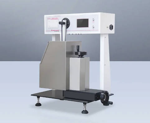
Product Samples We Regularly Subject to Glass Connection Strength Experiments
Our servo‑hydraulic test frames, reaction‑wall assemblies, environmental chambers, digital‑image‑correlation systems and calibrated load‑cells accommodate glass panels from a few hundred millimetres to full‑scale building‑floor heights. The following categories represent the most frequently tested items:
- Point‑fixed and bolted glass connections – stainless‑steel spider fittings, countersunk and button‑head bolted discs, articulated rotor fittings, and tension‑rod‑and‑cable‑net connectors for tempered and laminated safety glass
- Structural silicone and adhesive‑bonded glass joints – the silicone‑sealed edge‑seal of an insulating glass unit, the structural silicone of a flush‑glazed façade, and the two‑component epoxy or polyurethane adhesive bond between a glass fin and a metal bracket
- Mechanical clamps and clamped‑glazing assemblies – continuous aluminium or steel clamping profiles, patch‑plate fittings, glass‑retention clips and the bolted compression‑clamp systems used in balustrade and canopy glazing
- Undercut‑anchor and back‑bolt connections in glass – the cast‑in or the drilled‑and‑undercut anchor systems for monolithic tempered glass, and the laminated‑glass back‑bolt connections where the anchor passes through the interlayer
- Laminated‑glass insert and embedded‑fitting connections – the stainless‑steel or titanium insert plates that are laminated into the PVB or the ionomer interlayer, and the bolted connections that transfer the load from the glass to the insert
- Railing‑post, balustrade‑base and canopy‑support connections – the aluminium or steel shoe‑base fixings of a glass balustrade, the point‑fixing of a glass canopy to the overhead steelwork, and the glass‑beam‑to‑glass‑column connections in a structural glass pavilion
- Solar‑panel and photovoltaic‑module mounting‑rail‑to‑glass connections – the bonded or the clamped attachment of the mounting rail to the glass surface of a building‑integrated photovoltaic module
Point‑Fixed and Bolted Glass Connections – Glass Connection Strength Experiment According to ASTM C1401, EN 12898 and the Relevant National Standards
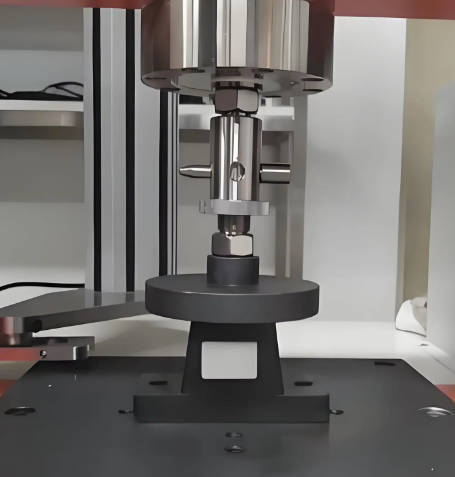
- Determination of the tensile pull‑out and the shear capacity of a point‑fixed fitting according to ASTM C1401 (Standard Guide for Structural Sealant Glazing) and the principles of EN 12898 (Glass in building – Determination of the emissivity): the fitting is mounted in a glass specimen that represents the actual pane thickness, the edge‑distance and the hole‑geometry, and a uniaxial tensile or a pure‑shear load is applied by a calibrated hydraulic actuator. The load‑displacement curve is recorded, and the maximum load, the failure mode – glass‑cone breakout, fitting‑yield or bolt‑pull‑through – and the residual deformation after the unload are reported. This glass connection strength experiment provides the characteristic resistance of the point‑fixing that the structural engineer uses to design the support layout and to calculate the safety factor for the glass element.
- Influence of the glass type, the temper and the hole‑finish on the connection strength: the test is repeated on annealed, heat‑strengthened and fully tempered glass, and with the drilled‑and‑countersunk, the water‑jet‑cut and the polished‑edge hole finishes. The data define the permissible glass‑processing specification for the point‑fixed connection and guide the selection of the most cost‑effective glass type for the project.
- Long‑term relaxation and the creep behaviour of the bolted connection under a sustained preload: a constant tensile load equal to a defined fraction of the short‑term ultimate capacity is applied to the fitting, and the displacement is monitored for up to 1 000 hours. The glass connection strength experiment determines the creep coefficient and the relaxation‑induced loss of the preload, and it verifies that the bolted connection will not loosen or lose its load‑carrying capacity over the service life of the building.
- Cyclic fatigue and the post‑fatigue residual strength of the glass connection: the fitting is subjected to a sinusoidal or a wind‑gust‑spectrum load for a specified number of cycles, and the residual ultimate capacity and the failure mode are remeasured. The test simulates the repeated wind‑suction, the thermal‑expansion and the pedestrian‑induced vibration loads on the point‑fixed façade, and it provides the fatigue‑endurance data that are required for the certification of the fitting for the tall‑building and the bridge‑canopy applications.
- Combined axial‑and‑shear and the multi‑directional loading of the articulated spider fittings: the fitting is loaded simultaneously in the tension and the shear, or at a prescribed angle to the glass plane, and the failure envelope in the tension–shear interaction space is constructed. This glass connection strength experiment supplies the data that the finite‑element analyst needs to model the real, three‑dimensional force transfer in a complex, curved‑glass structure.
Structural Silicone and Adhesive‑Bonded Glass Connections – Glass Connection Strength Experiment According to ASTM C1135, EN 15434 and ETAG 002
- Determination of the tensile, the shear and the peel adhesion of a structural silicone sealant to the glass and the metal substrate according to ASTM C1135 (Standard Test Method for Determining Tensile Adhesion of Structural Sealants) and EN 15434 (Glass in building – Product standard for structural and/or ultra‑violet resistant sealants): a lap‑shear or a butt‑joint specimen is prepared with the identical glass type, the metal profile, the primer and the sealant‑bead geometry that are specified for the project, and it is loaded to failure at a constant crosshead speed. The ultimate stress, the strain at break and the cohesive‑or‑adhesive failure mode are reported, and the result is compared with the allowable design stress for the sealant.
- Durability of the adhesive‑bonded glass connection after the immersion in the water, the exposure to the UV‑radiation and the thermal cycling: the bonded specimens are conditioned in the hot water, the xenon‑arc lamp or the temperature‑and‑humidity cycle before the mechanical test, and the retention of the adhesion strength is reported. This glass connection strength experiment verifies that the structural silicone or the adhesive will maintain its bond strength over the 25‑year or the 50‑year design life of the building envelope.
- Creep‑rupture and the long‑term static load test of the structural silicone joint under a sustained tensile or shear load: a constant load, equivalent to the design dead‑load plus a fraction of the wind‑load, is applied to the bonded joint for a minimum of 1 000 hours, and the time to the rupture or the accumulated creep displacement is recorded, providing the data that the engineer uses to set the safe working stress for the silicone and to calculate the long‑term deflection of the glass panel.
- Tensile‑adhesion and the cross‑cut test of the laminated‑glass insert and the interlayer‑bonded connection: the force required to pull a metal insert from the PVB or the ionomer interlayer is measured, and the failure mode – the interlayer‑tearing, the adhesive‑delamination or the glass‑breakage – is documented. This glass connection strength experiment qualifies the insert‑laminated glass for the load‑bearing railing, the canopy and the structural‑glass‑beam applications.
Mechanical Clamps, Balustrade‑Base and Embedded‑Channel Connections – Glass Connection Strength Experiment According to EN 1991‑1‑1, BS 6180 and the Structural‑Glass Design Guides
- Full‑scale static load test of a glass‑balustrade base‑shoe connection according to the principles of BS 6180 (Barriers in and about buildings – Code of practice) and the relevant national annexes: a complete glass‑panel‑and‑shoe assembly is bolted to a rigid test frame, and a horizontal line‑load or a uniformly distributed load is applied at the handrail height. The load‑deflection curve, the maximum load, the residual deflection after the unload and any cracking or failure of the glass, the shoe or the clamping‑blocks are recorded. The glass connection strength experiment certifies that the balustrade system meets the infill‑load and the barrier‑load requirements of the building code for the intended occupancy category.
- Testing of the clamping‑force retention and the slip‑resistance of the glass‑clamp assembly after the thermal cycling and the vibration exposure: the clamp is tightened to the design torque, and the assembly is subjected to a temperature‑cycle from -20 °C to +80 °C and a vibration‑frequency sweep. The residual clamp force and the displacement of the glass relative to the clamp are measured, providing the data that the installation engineer uses to specify the re‑tightening interval and to avoid the in‑service slip of the glass.
- Pull‑out and the shear capacity of the cast‑in channel and the post‑installed anchor connections in the concrete or the steel substructure that support the glass‑fitting: the connection between the point‑fixing and the primary building structure is tested as a complete assembly, and the failure mode – the anchor‑pull‑out, the channel‑lip‑fracture or the bolt‑rupture – is identified. This glass connection strength experiment ensures that the entire load‑path, from the glass pane to the building‑frame, possesses the required safety margin.
- Impact‑and‑post‑impact residual strength of the glass connection for the safety‑glazing applications: the glass panel is first impacted by a twin‑tyre or a soft‑body impactor according to the ECE R43 or the ANSI Z97.1 procedure, and then the connection is loaded to the failure. The test verifies that the connection retains its load‑carrying capacity after an accidental impact and that the glass will not fall from the frame.
Report Acceptance and Global Regulatory Compliance
All measurements performed within our glass connection strength experiment programme are executed under the fully accredited scope of our ISO/IEC 17025 quality management system. Each test report that carries the ILAC mark is therefore automatically recognised by regulatory authorities, notified bodies, customs offices and supply‑chain partners in all major economies. For structural‑glass designers, façade‑engineering consultancies, point‑fixing‑hardware manufacturers and building‑envelope contractors anywhere in the world, the report constitutes legally robust, internationally accepted evidence that the load‑bearing capacity, the fatigue resistance and the environmental durability of the glass connection have been determined in accordance with the applicable ASTM, EN, BS, AS and customer‑specified methods. The documentation can be directly used to support the CE marking of the glass product, the issuing of the Declaration of Performance, the obtaining of the national technical certificate for the glazing system, and the resolution of commercial and technical disputes concerning the structural performance and the safety of any glass‑connection assembly.