Fracture Toughness Testing Service – Accredited KIC, J‑Integral and CTOD Evaluation for Global Markets
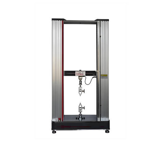
Our internationally accredited laboratory delivers a specialist fracture toughness testing service that provides structural engineers, pressure‑vessel manufacturers, pipeline operators, aerospace designers, welding engineers and materials researchers worldwide with the independent, traceable data required to assess the resistance of materials and components to unstable crack propagation. Every test is performed within the rigorous framework of ISO/IEC 17025, and each report bearing the ILAC mark is unconditionally accepted by regulatory authorities, notified bodies, customs offices and supply‑chain partners in all major economies. The fracture toughness testing service quantifies the critical stress‑intensity factor, the J‑integral and the crack‑tip opening displacement under plane‑strain and elastic‑plastic conditions, providing the fundamental material properties that underpin fitness‑for‑service assessments, damage‑tolerant design and the safe operation of critical infrastructure. By employing servo‑hydraulic test frames, environmental chambers, fatigue pre‑cracking, unloading‑compliance and direct‑current potential‑drop techniques, we deliver the legally robust, defensible fracture‑mechanics data that are mandatory for compliance with the Eurocodes, the ASME Boiler and Pressure Vessel Code and the relevant ISO and ASTM standards.
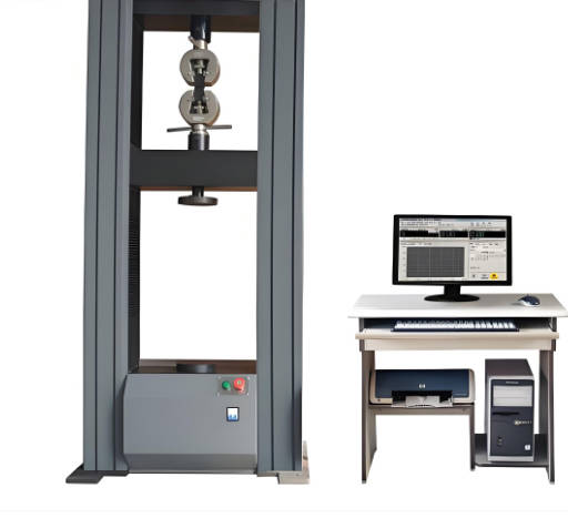
Product Samples We Regularly Subject to Fracture Toughness Testing
Our specimen‑preparation workshops and computer‑controlled test frames accommodate a wide variety of geometries, from compact‑tension and single‑edge‑notched‑bend specimens to full‑scale welded panels. The following categories represent the most frequently tested materials:
- Structural and pressure‑vessel steels – hot‑rolled plates, forgings, castings and weldments in grades S235 through S960, including subgrades with guaranteed toughness at low temperature
- Stainless steels and nickel‑base alloys – austenitic, duplex and super‑duplex stainless steels, Inconel, Hastelloy and Monel grades for chemical plant, offshore and power‑generation applications
- Aluminium, titanium and magnesium alloys – aerospace‑grade sheet, plate, extrusions and castings for airframes, landing gear and engine components
- Cast irons and sintered metals – grey iron, ductile iron, austempered ductile iron and powder‑metallurgy components
- Welded joints and heat‑affected zones – butt welds, fillet welds, repair welds and cladding on structural and pressure‑vessel steels
- Advanced ceramics and glass – alumina, zirconia, silicon nitride, silicon carbide, soda‑lime and borosilicate glass for armour, medical implants and electronic substrates
- Polymers and fibre‑reinforced composites – thermoplastics, thermosets, unidirectional laminates, woven‑fabric composites and sandwich cores
- Hardmetals, cermets and tool materials – cemented‑carbide blanks, mining inserts and wear parts
Metallic Materials – Fracture Toughness Testing Service According to ASTM E399, ASTM E1820 and ISO 12135
- Plane‑strain fracture toughness KIC according to ASTM E399 and ISO 12737: a compact‑tension or single‑edge‑notched‑bend specimen is fatigue pre‑cracked under strictly controlled ΔK conditions to produce a sharp, straight crack front. The specimen is loaded monotonically at a constant rate, and the force and crack‑opening displacement are recorded. The critical stress‑intensity factor KIC is calculated from the load at which the crack advances by a specified amount. Stringent validity checks on the specimen thickness, the crack length and the crack‑front straightness ensure that the result is a true, geometry‑independent material property. This fracture toughness testing service provides the benchmark value used by structural engineers to determine the maximum permissible flaw size in bridges, cranes and pressure vessels.
- J‑integral and the initiation fracture toughness JIC according to ASTM E1820: for ductile metals where large‑scale yielding precedes fracture, the elastic‑plastic J‑integral is measured using the single‑specimen unloading‑compliance method. The J‑R curve, which plots J against stable crack extension, is constructed, and the value of J at the initiation of stable tearing – JIC – is reported. The results are used in engineering critical assessments to predict the maximum tolerable crack size and to establish the margins against ductile tearing in pipelines, storage tanks and nuclear components.
- Crack‑tip opening displacement CTOD according to ISO 15653 and ASTM E1290: the critical crack‑tip opening displacement δc or δu is determined for base metals, weld metals and heat‑affected zones. The test is particularly valuable for structural steels that exhibit pop‑in behaviour, and the measured CTOD value is directly entered into the failure‑assessment diagrams of BS 7910, the FITNET procedure and the API 579‑1/ASME FFS‑1 standard. This parameter is the most widely requested toughness metric for offshore structures, Arctic pipelines and shipbuilding steels.
- Fracture toughness at low and elevated temperatures: the test is performed inside an environmental chamber that controls the temperature from -196 °C (liquid nitrogen) to +800 °C under an inert atmosphere. The shift in fracture toughness with temperature is measured, and the ductile‑to‑brittle transition curve is constructed, providing the mandatory input for the selection of steel subgrades for outdoor structures in cold climates and for high‑temperature components in power plants.
- Dynamic fracture toughness KId at high loading rates: for crash‑relevant automotive components, armour materials and structures subjected to impact, the fracture toughness is measured using an instrumented drop‑weight tower or a split‑Hopkinson pressure bar in bending configuration. The dynamic initiation toughness KId is reported as a function of the loading rate, supporting the crashworthiness simulations of vehicle structures and the design of blast‑resistant containers.
- Stress‑corrosion cracking and hydrogen‑embrittlement fracture toughness: pre‑cracked specimens are exposed to a corrosive environment – synthetic seawater, sour brine, ethanol‑blended fuel – or charged with hydrogen while being loaded under constant displacement or rising load. The threshold stress‑intensity factor KISCC or KIH is determined, below which sub‑critical crack growth will not occur during the design life. This fracture toughness testing service is critical for fasteners, springs, pipelines and pressure‑vessel components in the chemical, oil‑and‑gas and marine industries.
Ceramics and Glass – Fracture Toughness Testing Service for Brittle Materials According to ISO 15732 and ASTM C1421
- Determination of fracture toughness of advanced technical ceramics by the single‑edge‑pre‑cracked‑beam method according to ISO 15732 and ASTM C1421: a sharp pre‑crack is introduced into a bending bar by a bridge‑compression or a Vickers‑indentation method, and the specimen is loaded in four‑point bending. The fracture toughness KIC is calculated from the maximum load, the pre‑crack length and the specimen geometry. This fracture toughness testing service provides the primary quality‑control parameter for ceramic armour, cutting tools, medical implants and wear‑resistant components.
- Surface‑crack‑in‑flexure method according to ASTM C1421: a semi‑elliptical surface crack is generated by a Knoop indentation, and the specimen is loaded in bending until fracture. The method measures the fracture toughness of the surface layer, which is often the weakest region of a ceramic component due to machining damage or residual stress.
- Crack‑growth‑resistance curves and sub‑critical crack growth of ceramics: the crack velocity as a function of the applied stress intensity is measured in a controlled‑humidity or immersion environment. The parameters of the power‑law crack‑growth equation are determined, enabling the prediction of the lifetime of a ceramic component under sustained load – such as a dental implant, a furnace roller or a seal ring – from the proof‑test data.
- Weibull statistical analysis of the fracture‑toughness data: a minimum of 30 specimens are tested, and the characteristic toughness and the Weibull modulus are reported. The probability of failure at any given load is calculated, providing the design engineer with the statistically sound basis for setting the allowable stress in a brittle component.
Polymers, Composites and Adhesive Joints – Fracture Toughness Testing Service for Interlaminar and Bulk Resistance
- Plane‑strain fracture toughness KIC and GIC of plastics according to ISO 13586 and ASTM D5045: a single‑edge‑notched three‑point‑bend or compact‑tension specimen is pre‑cracked with a razor blade and loaded at a constant crosshead speed. The critical stress‑intensity factor KIC and the critical strain‑energy release rate GIC are calculated from the maximum load or from the load at which the crack becomes unstable. The values are used by injection‑moulders to compare grades of polycarbonate, acrylic, polyamide and polypropylene for impact‑critical applications.
- Interlaminar fracture toughness of composite laminates – Mode I GIC according to ISO 15024 and ASTM D5528: a double‑cantilever‑beam specimen with a pre‑implanted delamination is pulled apart, and the crack length is recorded optically or by compliance calibration. The resulting GIC value quantifies the resistance of the laminate to delamination, the dominant failure mode in aircraft wings, wind‑turbine blades and pressure vessels.
- Mixed‑mode and Mode II fracture toughness of composites according to ASTM D6671 and ISO 15114: end‑notched‑flexure specimens are loaded in three‑point bending to determine the Mode II interlaminar fracture toughness GIIC, and mixed‑mode bending tests provide the fracture envelope used in cohesive‑zone finite‑element models of bonded joints and delamination‑prone structures.
- Adhesive joint fracture toughness and cohesive‑zone characterisation: tapered double‑cantilever‑beam or end‑loaded‑split specimens are used to measure the fracture energy of structural adhesive bonds. The results are used to predict the debonding strength of automotive, aerospace and construction adhesive joints and to optimise the surface pre‑treatment and the adhesive formulation.
Welded Joints and Heat‑Affected Zones – Fracture Toughness Testing Service for Weld Procedure Qualification
- CTOD and KIC testing of weld metal and heat‑affected zone according to ISO 15653: a through‑thickness notch is precisely located in the weld metal, the coarse‑grained HAZ or the sub‑critical HAZ using micro‑hardness mapping or chemical etching. The specimen is fatigue pre‑cracked and loaded, and the CTOD or KIC at the first onset of stable tearing, pop‑in or brittle fracture is measured. This fracture toughness testing service is mandatory for the qualification of welding procedures for offshore structures, pressure vessels and submarine pipelines.
- Fracture toughness of high‑strength‑steel weldments: for crane booms, bridges and mobile equipment where quenched‑and‑tempered steels with yield strengths above 690 MPa are used, the fracture toughness of the weld and the HAZ is measured. The results confirm that the welding parameters do not degrade the toughness below the minimum specified for the base metal.
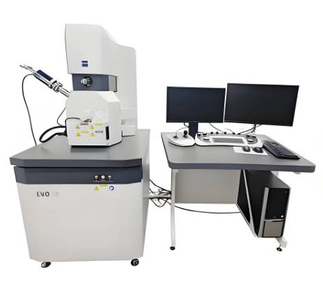
- Microstructural characterisation of the fracture path: after the test, a polished cross‑section is prepared through the crack, and the actual microstructure through which the crack propagated is identified by optical and electron microscopy. If the crack deviated from the target zone, the test is repeated with a revised notch location, ensuring that the reported toughness truly represents the weakest region of the joint.
- Weld‑metal hydrogen‑assisted cold‑cracking assessment: the implant test or the Tekken test is combined with fracture‑mechanics measurements to evaluate the threshold stress for hydrogen‑induced cracking in the HAZ, allowing fabricators to specify the correct pre‑heat and interpass temperatures for winter welding conditions.
Report Acceptance and Global Regulatory Compliance
All measurements performed within our fracture toughness testing service are executed under the fully accredited scope of our ISO/IEC 17025 quality management system. Each test report that carries the ILAC mark is therefore automatically recognised by regulatory authorities, notified bodies, customs offices and supply‑chain partners in all major economies. For steel producers, welding workshops, pressure‑vessel manufacturers, aerospace designers and polymer compounders anywhere in the world, the report constitutes legally robust, internationally accepted evidence that the fracture‑toughness values have been determined in accordance with the applicable ASTM, ISO, EN and customer‑specified methods. The documentation can be directly used for material certification, fitness‑for‑service assessments, the issue of inspection certificates according to EN 10204 or equivalent national standards, the qualification of welding procedures and the resolution of commercial and technical disputes concerning the resistance of materials to crack propagation.