Dynamic Core Experiment and Resistivity Experiment – Accredited Petrophysical and Electrical Property Evaluation for Global Oil and Gas Markets
Our internationally accredited laboratory delivers a comprehensive, integrated dynamic core experiment and resistivity experiment service that provides reservoir engineers, petrophysicists, drilling‑fluid formulators and enhanced‑oil‑recovery specialists worldwide with the coupled hydraulic and electrical data they need to accurately characterise the reservoir rock, predict hydrocarbon production and calibrate downhole log interpretation. Every test is conducted under the rigorous framework of ISO/IEC 17025, and each report bearing the ILAC mark is unconditionally accepted by regulatory authorities, notified bodies and supply‑chain partners in all major economies. The dynamic core experiment flows representative reservoir or injected fluids through a preserved or restored‑state core plug under precisely controlled overburden pressure, pore pressure, temperature and flow rate, continuously measuring the differential pressure, the permeability evolution, the filtrate loss and the relative permeability. The resistivity experiment simultaneously or sequentially determines the electrical formation resistivity factor, the resistivity index and the saturation exponent on the identical core material, providing the direct link between the fluid saturation and the electrical log response that is fundamental to the accurate estimation of the hydrocarbon in place.
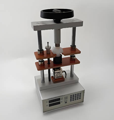
Product Samples We Regularly Subject to Dynamic Core and Resistivity Experiments
Our high‑pressure, high‑temperature core‑flooding systems equipped with four‑electrode resistivity cells, acoustic‑velocity transducers and precision metering pumps accommodate core plugs up to 1.5 inches in diameter and 3 inches in length. The following categories represent the most frequently evaluated materials:
- Reservoir‑rock core plugs – sandstone, carbonate, chalk, tight‑gas‑sand and shale core samples, either preserved at the native wettability or cleaned and restored to a defined saturation state
- Drilling‑fluid and reservoir‑drill‑in fluid formulations – water‑based, oil‑based and synthetic‑based muds that are circulated across the core face to deposit a filter cake and to evaluate the depth and the severity of the filtrate invasion
- Completion and workover fluids – clear brines, viscosified brines and solids‑free fluids whose dynamic filtration and formation‑damage potential are measured at the reservoir temperature
- Stimulation fluids – acidising formulations, scale‑dissolver treatments and hydraulic‑fracturing fluids that are injected into the core to assess the permeability improvement or the secondary‑precipitation damage
- Enhanced‑oil‑recovery agents – polymer, surfactant, alkaline and low‑salinity water formulations whose rheology, adsorption and incremental‑oil‑recovery performance are evaluated under the dynamic flow conditions
- Injectant gases and supercritical fluids – carbon dioxide, nitrogen and hydrocarbon gas that are flowed through the core to determine the relative permeability, the injectivity decline and the mineral‑reaction‑induced permeability alteration
Dynamic Core Experiment – Permeability, Formation Damage and Relative Permeability According to API RP 63 and ASTM D6524
- Dynamic filtration and return‑permeability testing of drilling and completion fluids according to the principles of API RP 63 and the internal protocols of the major oilfield operators: the core plug is saturated with a synthetic or a native reservoir brine, and the initial permeability to the formation fluid is measured at the reservoir‑confining pressure. The test fluid is then circulated across the core face at a controlled shear rate and overbalance pressure for a defined period while the filtrate volume and the differential pressure are continuously recorded. After the dynamic‑filtrate‑invasion phase, the production is reversed, and the return permeability is measured at several flow‑back rates. The percentage of the initial permeability that is recovered and the pressure required to initiate the back‑production are reported. This dynamic core experiment provides the quantitative formation‑damage metrics that the well‑construction engineer uses to compare the reservoir‑compatibility of different fluid candidates.
- Determination of the two‑phase oil‑water and gas‑oil relative permeability by the steady‑state and the unsteady‑state methods according to the principles of ASTM D6524 and the industry‑standard procedures: the core is brought to the irreducible water saturation or the residual oil saturation, and a simultaneous injection of oil and water at a fixed fractional flow is performed. The saturation is monitored by the gravimetric method or the in‑situ saturation‑profiling, and the relative permeability to each phase is calculated from the pressure drop and the flow rates. The relative‑permeability curves and the end‑point saturations are reported, providing the fundamental data that the reservoir‑simulation engineer uses to history‑match the production and to forecast the ultimate recovery.
- Dynamic core‑flooding for enhanced oil recovery – polymer, surfactant and alkaline‑surfactant‑polymer flooding: the core is flooded with a sequence of water, chemical slug and chase‑water, and the incremental oil recovery, the pressure‑drop profile and the chemical‑retention rate are measured. The dynamic core experiment quantifies the mobility‑control effectiveness, the interfacial‑tension reduction and the wettability alteration, supporting the design of the pilot‑scale and the field‑scale enhanced‑oil‑recovery projects.
- CO₂‑brine dynamic displacement and injectivity assessment for carbon‑capture‑and‑storage applications: supercritical carbon dioxide is injected into a brine‑saturated core at the reservoir pressure and temperature, and the pressure drop, the relative permeability and the displacement efficiency are measured. The test is continued for hundreds of pore‑volumes, and the injectivity decline caused by the salt precipitation, the fines migration and the mineral dissolution is monitored, providing the injectivity‑index data that the storage‑site operator uses to design the injection‑well completion.
Resistivity Experiment – Formation Resistivity Factor, Resistivity Index and Saturation Exponent According to ASTM D4784 and Archie's Law
- Determination of the formation resistivity factor FF and the cementation exponent m according to ASTM D4784 (Standard Test Method for Determination of Formation Resistivity Factor and Cementation Exponent of Porous Rocks) and the principles of Archie's law: the core plug is fully saturated with a brine of a known resistivity Rw, and its electrical resistance is measured by a four‑electrode or a two‑electrode system at the reservoir confining pressure and temperature. The resistivity of the fully water‑saturated rock Ro is calculated, and the formation resistivity factor FF = Ro / Rw is reported. The measurement is repeated at several brine salinities or on several plugs of a varying porosity, and the cementation exponent m is determined from the slope of the log(FF)‑versus‑log(porosity) plot. This resistivity experiment provides the essential parameter that the log analyst uses to convert the deep‑resistivity log reading to the formation‑water saturation.
- Determination of the resistivity index Ir and the saturation exponent n by the porous‑plate or the continuous‑injection method: the brine‑saturated core is desaturated in controlled steps by the injection of oil, air or a semi‑permeable membrane, and the electrical resistivity Rt at each partial water saturation Sw is measured. The resistivity index Ir = Rt / Ro is plotted against Sw on a log‑log scale, and the saturation exponent n is derived from the slope. The resistivity experiment directly measures the non‑linear relationship that governs the electrical‑log‑derived saturation, and it accounts for the effects of the wettability, the pore‑structure and the clay‑conductivity on the exponent n.
- Simultaneous dynamic‑flow and resistivity monitoring during the core‑flooding experiments: the electrical resistivity is continuously recorded along the length of the core by a multi‑electrode array during the dynamic filtrate‑invasion, the mud‑filtrate clean‑up and the oil‑displacement phases. The resistivity‑profile evolution and the final resistivity distribution are reported, providing the direct calibration of the invasion‑correction algorithms and the time‑lapse resistivity logs.
- Influence of the stress, the temperature and the clay‑cation‑exchange on the electrical properties: the formation resistivity factor and the saturation exponent are measured at a series of confining pressures and temperatures that span the reservoir‑depletion and the thermal‑recovery range, and the effect of the clay‑bound water on the excess conductivity is quantified by the Waxman‑Smits or the dual‑water model parameters, providing the data that the petrophysicist needs to correctly interpret the shaly‑sand reservoirs.
- Capillary‑pressure and resistivity combined measurement – the equilibrium porous‑plate method: a multi‑step drainage capillary‑pressure curve is obtained simultaneously with the resistivity index on the same core plug, establishing the direct, point‑by‑point correlation between the capillary pressure, the water saturation and the electrical resistivity that is required for the accurate height‑above‑free‑water‑level saturation modelling.
Report Acceptance and Global Regulatory Compliance
All measurements performed within our dynamic core experiment and resistivity experiment programme are executed under the fully accredited scope of our ISO/IEC 17025 quality management system. Each test report that carries the ILAC mark is therefore automatically recognised by regulatory authorities, notified bodies, customs offices and supply‑chain partners in all major economies. For oil‑and‑gas operating companies, petrophysical consultancies, drilling‑fluid and completion‑fluid manufacturers and enhanced‑oil‑recovery chemical suppliers anywhere in the world, the report constitutes legally robust, internationally accepted evidence that the permeability, the formation‑damage potential, the relative‑permeability characteristics, the formation resistivity factor, the resistivity index and the saturation exponent of the reservoir rock have been determined in accordance with the applicable API, ASTM, ISO and customer‑specified methods. The documentation can be directly used to support the field‑development plan approval, the reserves‑booking audit, the well‑construction permit, the issue of inspection certificates according to EN 10204 or equivalent national standards, and the resolution of commercial and technical disputes concerning the petrophysical and the electrical properties of any reservoir formation.