Charge Sensitivity Testing Service – Accredited Calibration and Evaluation of Piezoelectric Sensors and Charge Amplifiers for Global Markets
Our internationally accredited laboratory delivers a specialist charge sensitivity testing service that provides manufacturers of piezoelectric accelerometers, pressure transducers, force sensors, vibration monitors and charge amplifiers worldwide with the independent, traceable data required to verify the electromechanical conversion performance of their devices. Every test is performed within the rigorous framework of ISO/IEC 17025, and each report bearing the ILAC mark is unconditionally accepted by regulatory authorities, notified bodies and supply‑chain partners in all major economies. The charge sensitivity testing service quantifies the fundamental output characteristic of a piezoelectric sensor – the charge in picocoulombs generated per unit of the measured physical quantity, such as acceleration (pC/g or pC/m/s²), pressure (pC/bar) or force (pC/N). By employing calibrated reference accelerometers, precision shakers, charge‑amplifier standards, high‑input‑impedance meters and environmental chambers, we measure the charge sensitivity, the frequency response, the linearity, the transverse sensitivity and the temperature coefficient of the sensor, providing the legally robust, defensible data that support product certification, ISO 9001 quality‑system compliance and the reliable operation of condition‑monitoring, modal‑analysis and aerospace‑instrumentation systems on every continent.
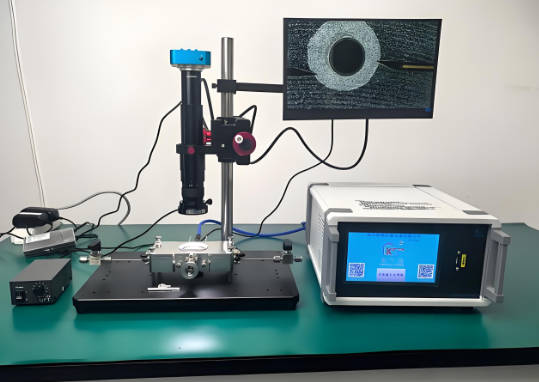
Product Samples We Regularly Subject to Charge Sensitivity Testing
The back‑to‑back calibration shakers, charge‑amplifier calibration benches and climatic chambers in our facility accommodate sensors from miniature integrated‑circuit piezoelectric chips to industrial‑grade transducers. The following categories represent the most frequently tested items:
- Piezoelectric accelerometers – shear‑mode, compression‑mode and flexural‑beam accelerometers for general‑purpose vibration monitoring, modal analysis, seismic surveying and aerospace flight‑flutter testing
- Piezoelectric pressure transducers – miniature pencil‑type pressure sensors for engine‑cylinder and turbine‑combustor measurement, dynamic‑pressure probes for shock‑tube studies and ballistics
- Piezoelectric force sensors and load washers – pre‑loaded force rings, impact‑force hammers and multi‑component dynamometers for machining‑force measurement and material‑testing
- Charge amplifiers and signal conditioners – laboratory‑grade and industrial charge amplifiers, inline charge converters, and the charge‑input channels of data‑acquisition systems
- Integrated electronic piezoelectric sensors (IEPE) with charge‑mode verification: sensors that normally output a voltage signal but can be tested in their raw charge‑mode configuration before the integrated amplifier
- Piezoelectric hydrophones and underwater acoustic transducers: devices for which the charge sensitivity in pC/µPa must be measured in a calibrated underwater acoustic tank
- Micro‑electromechanical system piezoelectric sensors: MEMS accelerometers and pressure sensors on silicon chips where the charge sensitivity is a critical design‑validation parameter
Charge Sensitivity Testing Service for Piezoelectric Accelerometers – Calibration According to ISO 16063‑21 and ISO 5347 Series
- Determination of the reference charge sensitivity of an accelerometer by back‑to‑back comparison according to ISO 16063‑21 (Primary vibration calibration by laser interferometry and secondary vibration calibration by comparison) and the ISO 5347 series: the test accelerometer is mounted on a reference accelerometer of known, traceable charge sensitivity, and the assembly is attached to a precision electrodynamic shaker. The shaker excites the assembly at a defined frequency – typically 80 Hz or 160 Hz – and a controlled acceleration amplitude of 100 m/s². The charge output of the test accelerometer is measured by a calibrated charge amplifier, and the reference charge sensitivity at the calibration frequency is calculated. The result is reported in picocoulombs per metre per second squared (pC/m/s²) or in picocoulombs per g (pC/g). This charge sensitivity testing service provides the primary calibration data that are mandatory for the traceable measurement of vibration in aerospace, automotive and power‑generation applications.
- Frequency‑response measurement of charge sensitivity over the full usable bandwidth according to ISO 16063‑21 and customer‑specific protocols: the shaker performs a swept‑sine or a stepped‑sine excitation from a low frequency – as low as 0.5 Hz for seismic accelerometers – up to the mounted resonant frequency of the sensor, often 10 kHz, 20 kHz or higher. The charge sensitivity is recorded at each frequency step, and the deviation from the reference sensitivity is plotted as a percentage. The ±5 %, ±10 % and ±3 dB bandwidths are reported, providing the data that the test engineer uses to select the correct sensor for the frequency range of the target measurement.
- Linearity and dynamic‑range characterisation of the charge sensitivity: the acceleration amplitude is increased in steps from a low value – typically 10 m/s² – up to the full‑scale range of the sensor or the shaker, and the charge sensitivity at each amplitude is measured. The linearity error in percent of full scale is reported, and any amplitude‑dependent sensitivity shift is identified. This charge sensitivity testing service verifies that the sensor will not saturate or produce a distorted output under the high‑shock or high‑vibration conditions encountered in crash testing, rocket‑launch monitoring and heavy‑industrial machinery.
- Transverse charge sensitivity and cross‑axis response measurement according to ISO 16063‑31: the accelerometer is mounted on a transverse‑excitation fixture, and the charge output in response to a vibration applied perpendicular to the sensitive axis is measured. The transverse sensitivity, expressed as a percentage of the axial sensitivity, is reported. A low transverse sensitivity – typically below 5 % – is critical for the accurate measurement of vibration on structures where the direction of motion is unknown or multi‑axial.
- Temperature‑coefficient measurement of the charge sensitivity: the accelerometer is placed in a climatic chamber on the shaker, and the charge sensitivity is measured at a series of temperatures from -55 °C to +250 °C or higher, depending on the sensor construction. The temperature coefficient of the sensitivity in percent per degree Celsius is reported, and the data are used to correct the measured charge for the ambient temperature at the measurement site, which is essential for in‑situ vibration monitoring on jet engines, steam turbines and spacecraft.
- Base‑strain and magnetic‑field sensitivity evaluation: the accelerometer is mounted on a bending beam, and the charge output caused by the strain of the mounting surface without any intentional acceleration is recorded. The base‑strain sensitivity in pC/µε is reported. Similarly, the sensor is exposed to a known alternating magnetic field, and any spurious charge output is quantified, ensuring that the accelerometer will not produce false signals when used near electric motors, generators or magnetic bearings.
Charge Sensitivity Testing Service for Pressure Transducers, Force Sensors and Hydrophones – Specialised Dynamic Calibration
- Determination of the charge sensitivity of piezoelectric pressure transducers by dynamic‑pressure comparison according to the principles of ISO 17088 and internal procedures: the test transducer is installed in a calibrated pressure‑pulse generator or a comparison tube, and a step‑change or a sinusoidal pressure signal is applied. The charge output is measured by a calibrated charge amplifier, and the charge sensitivity in picocoulombs per bar or pC/Pa is calculated. The test includes the measurement of the rise‑time response and the resonant frequency of the transducer, providing the data that ballistic‑range operators and engine‑combustion analysts use to ensure the fidelity of the pressure‑time record.
- Calibration of piezoelectric force transducers and impact hammers: the sensor is loaded in a calibrated force‑generating machine, and the charge output is recorded at several force steps. The charge sensitivity in pC/N and the linearity are reported. For impact hammers, the charge sensitivity of the built‑in force sensor is determined by a pendulum‑impact comparison with a reference force transducer, and the data are used to set up the modal‑analysis measurement chain.
- Charge sensitivity of piezoelectric hydrophones in an underwater acoustic test facility: the hydrophone is immersed in a water‑filled tank, and a calibrated projector generates a known sound‑pressure level at a specified frequency. The charge output of the hydrophone is measured, and the charge sensitivity in pC/µPa is reported. This charge sensitivity testing service supports the certification of hydrophones for ocean‑acoustic monitoring, seismic‑survey streamers and naval sonar systems.
- Charge‑mode sensitivity of multi‑component dynamometers and load‑cells: the three orthogonal charge outputs of the dynamometer are measured while a known force vector is applied, and the direct and cross‑talk sensitivities in pC/N are reported. The data are used to construct the sensitivity matrix that the data‑acquisition software uses to resolve the three force components.
Charge Sensitivity Testing Service for Charge Amplifiers and Signal‑Conditioning Systems – Gain, Linearity and Noise Characterisation
- Determination of the gain and the transfer factor of a charge amplifier according to the principles of IEC 60751 (for industrial platinum resistance thermometers, adapted for charge‑amplifier calibration) and internal calibration procedures: a precision charge generator or a calibrated capacitor is used to inject a known charge into the input of the charge amplifier, and the output voltage is measured. The gain factor in millivolts per picocoulomb (mV/pC) is calculated, and the deviation from the nominal gain is reported. This charge sensitivity testing service ensures that the charge amplifier is calibrated to produce the correct voltage output for a given input charge, closing the traceability chain from the sensor to the digital‑data recorder.
- Frequency response and bandwidth verification of the charge‑amplifier channel: the charge generator injects a sinusoidal charge signal at frequencies from 0.1 Hz to 200 kHz, and the output voltage is recorded. The -3 dB upper and lower cut‑off frequencies are reported, together with the phase shift as a function of frequency. The data are used to select the correct low‑pass filter setting and to avoid signal distortion in the frequency range of interest.
- Noise‑floor and drift measurement of the charge‑amplifier input: the input of the charge amplifier is terminated with a source capacitance that simulates the connected piezoelectric sensor, and the broadband and 1/f‑noise of the output are measured. The noise floor expressed as an equivalent input charge in femtocoulombs is reported, providing the data that the test engineer needs to determine the minimum detectable signal of the measurement chain.
- Time‑constant and low‑frequency response verification: a charge step is injected, and the exponential decay of the output voltage is recorded. The discharge time constant of the charge amplifier is calculated, and the low‑frequency response is verified. This test is critical for the correct measurement of quasi‑static pressure and force events, such as the firing‑pressure curve in a large‑calibre gun or the preload‑relaxation curve in a bolted joint.
- Combined calibration of the sensor–charge‑amplifier chain: the complete measurement chain, from the piezoelectric sensor through the charge amplifier to the output connector, is calibrated as a single unit. The chain sensitivity in millivolts per engineering unit (mV/g, mV/bar, mV/N) is reported, and the expanded measurement uncertainty of the complete chain is stated. This charge sensitivity testing service provides the most direct traceability for the end‑user, who simply connects the output to a voltmeter or an analyser.
Report Acceptance and Global Regulatory Compliance
All measurements performed within our charge sensitivity testing service are executed under the fully accredited scope of our ISO/IEC 17025 quality management system. Each test report that carries the ILAC mark is therefore automatically recognised by regulatory authorities, notified bodies, customs offices and supply‑chain partners in all major economies. For manufacturers of piezoelectric sensors, charge amplifiers and vibration‑monitoring systems anywhere in the world, the report constitutes legally robust, internationally accepted evidence that the charge sensitivity, the frequency response, the linearity and the environmental coefficients of the device have been determined in accordance with the applicable ISO 16063, IEC and customer‑specified methods. The documentation can be directly used to support CE marking, the issue of inspection certificates according to EN 10204 or equivalent national standards, the compilation of technical files for type‑examination, and the resolution of commercial and technical disputes concerning the sensitivity and the electromechanical performance of piezoelectric sensors and charge‑conditioning electronics.