Armature Thermal Resistance Testing Service – Accredited Heat Dissipation and Temperature Rise Evaluation for Global Markets
Our internationally accredited laboratory provides a specialist armature thermal resistance testing service that enables manufacturers of electric motors, generators, alternators, solenoid actuators, relay coils and electromagnetic clutches worldwide to verify the thermal performance, insulation integrity and cooling efficiency of their rotating and linear armature assemblies. Every measurement is conducted within the rigorous framework of ISO/IEC 17025, and each report bearing the ILAC mark is unconditionally accepted by regulatory authorities, notified bodies and supply‑chain partners in all major economies. The armature thermal resistance testing service quantifies the temperature rise, the thermal resistance from winding to ambient, the heat‑dissipation coefficient and the thermal time constant of the armature under defined electrical loading and cooling conditions. For a motor manufacturer certifying a traction‑motor armature to insulation class H, a solenoid producer guaranteeing the duty cycle of an industrial valve, or a generator rewinder verifying the thermal performance after a repair, our platform delivers the legally robust, defensible data that underpin product certification, warranty validation and compliance with the relevant IEC, IEEE, NEMA and customer‑specified standards.
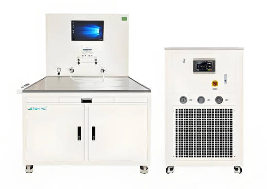
Product Samples We Regularly Subject to Armature Thermal Resistance Testing
Our programmable DC and AC power supplies, thermocouple data‑loggers, thermal‑imaging cameras and environmental chambers accommodate armatures from miniature coreless motors to large industrial‑generator rotors. The following categories represent the most frequently tested items:
- DC motor armatures – slotted and slotless armatures for permanent‑magnet, series‑wound and shunt‑wound motors used in automotive starters, electric power steering, power tools and industrial drives
- AC stator and rotor windings – form‑wound coils, random‑wound mush coils, and bar‑type windings for induction motors, synchronous generators and alternators
- Solenoid and relay armatures – push‑type and pull‑type solenoid plungers, relay armature‑and‑coil assemblies, and proportional‑valve actuators
- Eddy‑current clutch and brake armatures – excitation coils and armature drums for industrial tension‑control and dynamometer applications
- Voice‑coil actuator armatures – moving‑coil assemblies for linear positioning stages, optical‑scanner galvanometers and loudspeaker drivers
- Rewound and refurbished armatures – repaired motor and generator armatures that require verification of the thermal resistance after the rewinding and impregnation process
- Armature coil samples and encapsulated windings – single coils, potted coil assemblies and epoxy‑encapsulated stators for submersible pumps, aerospace actuators and down‑hole oilfield tools
Armature Thermal Resistance Testing Service for Electric Motors and Generators – Temperature Rise and Thermal Resistance According to IEC 60034‑1 and IEEE 112
- Determination of the steady‑state temperature rise and the winding thermal resistance by the resistance method according to IEC 60034‑1 (Rotating electrical machines – Rating and performance) and IEEE 112 (Standard Test Procedure for Polyphase Induction Motors and Generators): the armature winding is energised at the rated voltage or current, and the machine is loaded to the specified output. The winding resistance is measured at the beginning and at the end of the thermal‑stabilisation period using a precision four‑terminal Kelvin bridge. The temperature rise ΔT is calculated from the increase in resistance and the temperature coefficient of copper, and the thermal resistance Rth in kelvins per watt is computed as ΔT divided by the total winding loss. This armature thermal resistance testing service provides the fundamental data that motor designers use to verify the cooling design, to select the correct insulation class and to ensure that the hot‑spot temperature does not exceed the limit for the winding insulation.
- Thermal‑mapping of the armature surface and the commutator or slip‑rings by thermocouple and infrared‑thermography: an array of embedded thermocouples and a high‑resolution thermal‑imaging camera record the temperature distribution across the armature core, the end‑windings and the commutator segments during the test. The location of the hottest spot, the temperature gradient and the cooling asymmetry are identified, and the data are used to refine the winding layout, the impregnation process and the air‑duct geometry.
- Measurement of the thermal time constant of the armature according to the principles of IEC 60034‑1 Annex E: the armature is heated from cold to the steady‑state temperature while the winding resistance is continuously recorded. The thermal time constant τth – the time to reach 63.2 % of the final temperature rise – is extracted from the exponential heating curve, and the data are reported. The thermal time constant is the key parameter for predicting the short‑time overload capability of the motor and for setting the correct protection‑relay tripping characteristics.
- Determination of the armature thermal resistance under different cooling‑air velocities and ambient temperatures: the test is repeated at several cooling‑fan speeds or with the armature installed in a wind tunnel, and the dependence of the thermal resistance on the air flow is reported. The data enable the system integrator to predict the motor temperature under the actual ventilation conditions of the final installation, whether it be a tightly‑packed machine cabinet or a well‑ventilated open deck.
- Thermal‑ageing and heat‑cycling endurance of the armature insulation system: the armature is subjected to repeated heating and cooling cycles while the insulation resistance, the polarisation index and the dielectric strength are monitored. This armature thermal resistance testing service verifies that the thermal expansion and contraction of the copper and the iron do not cause delamination, cracking or loss of the impregnating varnish, and it supports the qualification of the insulation system to the thermal class (130 °C, 155 °C, 180 °C, 200 °C) required by IEC 60034‑18‑21 or IEEE 1776.
- Locked‑rotor and stall‑current temperature‑rise test: the rotor is mechanically locked, and the rated voltage is applied for a defined short duration. The rate of temperature rise of the winding and the thermal resistance under the stalled condition are reported, providing the data that the motor‑protection engineer needs to set the maximum permissible stall time before the insulation is damaged.
Armature Thermal Resistance Testing Service for Solenoids, Relays and Electromagnetic Actuators – Duty‑Cycle and Coil‑Temperature Verification
- Determination of the coil temperature rise and the thermal resistance of solenoid and relay armatures according to the principles of IEC 61810‑7 (Electromechanical elementary relays – Tests and measurements) and the relevant automotive OEM standards: the coil is energised with the rated voltage at the specified duty cycle, and the coil resistance is measured at intervals by a high‑precision multimeter. The temperature rise and the steady‑state thermal resistance Rth are calculated. This armature thermal resistance testing service verifies that the coil will not overheat and that the insulation of the magnet wire will not degrade during the intended service life of the solenoid valve, the door‑lock actuator or the starter relay.
- Measurement of the hot‑pull and hot‑hold characteristics of a solenoid as a function of the armature temperature: the solenoid is heated to the maximum service temperature, and the force‑versus‑stroke curve and the minimum holding voltage are measured. The reduction in the force output caused by the increased coil resistance and the decreased magnetic permeability is quantified, providing the data that the system designer uses to guarantee the reliable operation of the solenoid under hot‑soak conditions.
- Thermal‑time‑constant and duty‑cycle verification for intermittent‑duty actuators: the coil temperature is monitored during a sequence of on‑and‑off cycles that represent the actual operating mode, and the thermal time constant of the armature coil is extracted. The maximum allowed duty cycle at each ambient temperature is reported, ensuring that the actuator will not be operated beyond its thermal capability in the field.
- Thermal‑resistance testing of voice‑coil actuator armatures and moving‑magnet linear motors: the coil assembly is energised at a constant current, and the temperature of the winding is measured by a non‑contact infrared sensor or an embedded miniature thermocouple. The thermal resistance from the coil to the ambient air or to the water‑cooling jacket is reported, and the data are used to set the continuous‑force rating and the peak‑force duration of the actuator for precision‑positioning applications.
- Post‑impregnation and post‑encapsulation thermal‑resistance verification: the thermal resistance of the armature is measured before and after the vacuum‑pressure impregnation or the epoxy‑encapsulation process. A significant decrease in the thermal resistance confirms that the impregnating resin has effectively filled the air voids in the winding and improved the heat transfer from the copper to the stator or the housing, directly demonstrating the quality of the manufacturing process.
Report Acceptance and Global Regulatory Compliance
All measurements performed within our armature thermal resistance testing service are executed under the fully accredited scope of our ISO/IEC 17025 quality management system. Each test report that carries the ILAC mark is therefore automatically recognised by regulatory authorities, notified bodies, customs offices and supply‑chain partners in all major economies. For motor manufacturers, solenoid and relay producers, generator refurbishers and precision‑actuator designers anywhere in the world, the report constitutes legally robust, internationally accepted evidence that the thermal resistance, the temperature rise and the thermal time constant of the armature have been determined in accordance with the applicable IEC, IEEE, NEMA and customer‑specified methods. The documentation can be directly used to support CE marking, the issue of inspection certificates according to EN 10204 or equivalent national standards, the compilation of technical files for type‑examination, and the resolution of commercial and technical disputes concerning the thermal performance and the insulation‑system integrity of any armature or wound component.