Armature Inertia Testing Service – Accredited Moment of Inertia and Rotordynamic Evaluation for Global Markets
Our internationally accredited laboratory delivers a specialist armature inertia testing service that enables electric motor manufacturers, generator producers, servo‑system designers, flywheel‑energy‑storage developers, and precision‑engineering companies worldwide to measure the mass moment of inertia, the radius of gyration, and the dynamic balance characteristics of their rotating armatures and wound rotors. Every measurement is performed within the strict framework of ISO/IEC 17025, and each report bearing the ILAC mark is unconditionally accepted by regulatory authorities, notified bodies, and supply‑chain partners in all major economies. The armature inertia testing service employs bifilar torsion pendulums, trifilar suspension rigs, torsional oscillation tables, and spin‑down dynamometers to quantify the moment of inertia and the inertial torque developed by a component during acceleration or deceleration. For a traction‑motor manufacturer optimising the rotor design for rapid torque response, an aerospace generator supplier certifying the inertia of a high‑speed armature, or a servo‑motor integrator tuning the control‑loop parameters, our platform provides the legally robust, traceable inertia data that underpin system‑performance predictions, vibration‑analysis calculations and compliance with the relevant IEC, IEEE, SAE and customer‑specified standards.
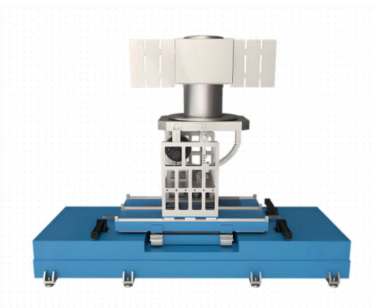
Product Samples We Regularly Test Using Our Armature Inertia Testing Service
Our torsion‑pendulum rigs, spin‑down test stands, and computer‑aided data‑acquisition systems accommodate armatures and rotors ranging from miniature coreless motor windings to large industrial generator rotors. The following categories represent the most frequently tested items:
- DC motor armatures – slotted and slotless armatures with commutators for permanent‑magnet, series‑wound, and shunt‑wound motors used in automotive starters, power tools, electric‑power‑steering actuators, and industrial servo drives
- AC induction motor rotors – squirrel‑cage rotors with aluminium, copper, or fabricated‑bar constructions for industrial motors, pump drives, and compressor applications
- Permanent‑magnet synchronous motor rotors – interior‑permanent‑magnet and surface‑mounted‑magnet rotors for electric‑vehicle traction motors, elevator machines, and direct‑drive wind‑turbine generators
- Turbo‑generator and hydro‑generator rotors – cylindrical forged‑steel rotors and salient‑pole rotors for power‑station generators, including the complete wound‑field assembly with retaining rings
- Flywheel and energy‑storage armatures – composite‑rim and steel‑alloy flywheel rotors for uninterruptible power supplies, grid‑frequency regulation, and kinetic‑energy recovery systems
- Voice‑coil and moving‑magnet actuator armatures – moving‑coil forcers and tubular actuator armatures for precision positioning stages, optical scanners, and vibration‑test exciters
- Electromagnetic clutch and brake armatures – armature plates and rotor discs for industrial tension‑control clutches, automotive air‑conditioning clutches, and electromagnetic braking systems
- Prototype and additively manufactured armatures – 3D‑printed rotor cores, topology‑optimised armature designs, and composite‑material experimental rotors for which the moment of inertia must be verified against the design model
Armature Inertia Testing Service – Determination of the Mass Moment of Inertia by the Bifilar and Trifilar Torsion‑Pendulum Methods
- Measurement of the moment of inertia about the rotational axis using a bifilar or trifilar torsion pendulum according to the principles of ISO 29658 (Mechanical vibration and shock – Measurement of the moment of inertia) and ASTM E1526: the armature is suspended from two or three parallel wires of known length and spacing, and the assembly is set into small‑amplitude torsional oscillation. The period of oscillation is measured by an optical sensor or an accelerometer, and the moment of inertia is calculated from the period, the suspension geometry, the wire tension, and the mass of the armature. The result is reported in kilogram‑metres squared (kg·m²) or gram‑centimetres squared (g·cm²). This armature inertia testing service provides the fundamental inertia data that control‑system designers use to calculate the mechanical time constant, the torque‑to‑inertia ratio, and the acceleration profile of the motor‑driven axis.
- Spin‑down deceleration method for large and high‑speed armatures according to the principles of ASTM E620 and internal procedures: the armature is mounted on a low‑friction aerostatic or ball‑bearing spindle and accelerated to a defined rotational speed. The driving torque is then removed, and the deceleration rate is recorded by a high‑resolution encoder or a tachometer. The moment of inertia is determined from the known frictional torque of the spindle and the angular deceleration, applying Newton's second law for rotation. The method is particularly suited to large generator rotors and flywheels that exceed the capacity of a torsion pendulum.
- Torsional‑oscillation table method for heavy and complex‑shaped armatures: the armature is rigidly attached to a calibrated torsional spring or a torsional dynamometer, and the natural frequency of the spring–mass system is measured. The moment of inertia is calculated from the natural frequency and the known torsional stiffness of the spring. This armature inertia testing service accommodates asymmetric rotors, salient‑pole generator fields, and armatures with irregular mass distributions that cannot be easily suspended on wires.
- Computer‑aided determination of the moment of inertia from a three‑dimensional CAD model, validated by physical measurement: the physical inertia measurement is compared with the value predicted by the solid‑modelling software, and the deviation is reported. The data close the loop between the design intent and the manufactured component, enabling the production engineer to identify deviations in material density, casting porosity, or machining stock that affect the rotational dynamics.
- Measurement of the inertia tensor and the products of inertia for high‑speed rotordynamic balancing: the armature is tested in multiple orientations on a trifilar pendulum or a specialised inertia‑measurement machine, and the complete inertia tensor – the moments of inertia about the three principal axes and the products of inertia – is reported. The data are essential for the accurate prediction of the critical speeds, the gyroscopic moments, and the bearing loads of high‑speed motors, turbochargers, and gas‑turbine generators.
Armature Inertia Testing Service for Electric‑Vehicle Traction Motors and Servo Systems – Torque‑to‑Inertia Ratio and Control‑Loop Optimisation
- Determination of the rotor moment of inertia and the torque‑to‑inertia ratio for permanent‑magnet synchronous motors: the inertia of the rotor assembly – including the laminations, the magnets, the shaft, and the resolver or encoder rotor – is measured by the torsion‑pendulum or spin‑down method. The torque‑to‑inertia ratio T/J in N·m/kg·m² is calculated, and the result is compared with the design target. This armature inertia testing service provides the critical data that traction‑motor designers use to optimise the rotor geometry for maximum dynamic responsiveness and minimum energy consumption in electric‑vehicle applications.
- Influence of the armature inertia on the closed‑loop bandwidth and the settling time of a servo axis: the measured inertia is entered into the servo‑drive’s auto‑tuning algorithm or into a simulation model, and the predicted bandwidth, the settling time, and the following error are verified by a subsequent motion test. The inertia data allow the drive engineer to set the correct current‑loop and velocity‑loop gains and to avoid the instability that results from a mismatch between the controller parameters and the actual rotor inertia.
- Inertia matching and load‑to‑motor inertia ratio for precision positioning systems: the armature inertia is compared with the reflected inertia of the driven load, and the inertia ratio J_load / J_motor is reported. A ratio in the range of 1:1 to 10:1 is typically recommended for servo applications, and the data are used to select the correct gearbox ratio, to specify the coupling stiffness, and to prevent resonance and overshoot in machine‑tool axes, pick‑and‑place robots, and semiconductor‑wafer handlers.
- Measurement of the inertia change due to the addition of cooling‑fan impellers, brake discs, and encoder components: the moment of inertia of the bare armature is measured first, and then the inertia of the fully assembled rotating group – including the fan, the brake, and the feedback devices – is measured. The contribution of each auxiliary component is quantified, ensuring that the total inertia remains within the permissible limit for the motor frame size and the thermal class.
Armature Inertia Testing for Power‑Generation and Heavy‑Industrial Rotors – Balancing and Critical‑Speed Prediction
- Determination of the polar moment of inertia of generator and motor rotors for the calculation of the acceleration time and the starting current: the inertia is measured by the bifilar‑pendulum or the spin‑down method, and the result is reported in kg·m². The data are used by the power‑system engineer to calculate the rotor’s acceleration time under the influence of the electrical torque, to set the under‑frequency load‑shedding relays, and to predict the voltage‑dip during the starting of a large induction motor on a weak grid.
- Inertia measurement for multi‑rotor and multi‑stage rotating assemblies – compressor‑turbine‑generator strings: each individual rotor element is measured separately, and the total inertia of the assembled string is verified against the summation of the individual inertias. This armature inertia testing service supports the dynamic analysis of coupled torsional modes in long shaft lines and ensures that the torsional natural frequencies do not coincide with the excitation frequencies of the electrical grid or the compressor blades.
- Measurement of the moment of inertia of the rotor for the calculation of the critical speeds and the response to unbalanced excitation: the inertia, together with the shaft stiffness and the bearing characteristics, is used in a rotordynamic finite‑element model to predict the first, second, and higher critical speeds of the machine. The measured inertia validates the model, ensuring that the critical speeds are sufficiently separated from the operating‑speed range and that the vibration levels will remain within the acceptance limits defined by ISO 20816‑1 and the relevant machine‑specific standards.
- Inertia measurement of the flywheel and the exciter‑armature of synchronous generators for grid‑stability studies: the inertia constant H in seconds – the ratio of the stored kinetic energy at rated speed to the rated apparent power – is reported, providing the parameter that the transmission‑system operator requires to model the frequency‑response capability of the generating unit and to guarantee the stability of the grid.
Report Acceptance and Global Regulatory Compliance
All measurements performed within our armature inertia testing service are executed under the fully accredited scope of our ISO/IEC 17025 quality management system. Each test report that carries the ILAC mark is therefore automatically recognised by regulatory authorities, notified bodies, customs offices, and supply‑chain partners in all major economies. For motor manufacturers, generator producers, servo‑system integrators, flywheel‑storage developers, and precision‑engineering companies anywhere in the world, the report constitutes legally robust, internationally accepted evidence that the moment of inertia, the radius of gyration, and the related rotordynamic parameters of the armature have been determined in accordance with the applicable ISO, ASTM, IEC, IEEE, SAE, and customer‑specified methods. The documentation can be directly used to support CE marking, the issue of inspection certificates according to EN 10204 or equivalent national standards, the compilation of technical files for type‑examination, and the resolution of commercial and technical disputes concerning the inertial characteristics and the dynamic performance of any rotating armature or rotor.