Accelerated Cold and Hot Cycle Test – Accredited Thermal Shock and Rapid Temperature Change Evaluation for Global Markets
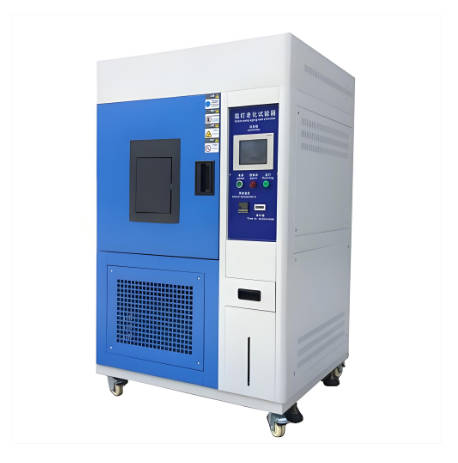
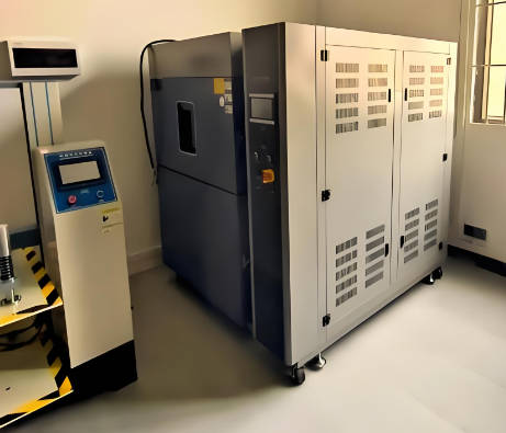
Our internationally accredited laboratory provides a specialist accelerated cold and hot cycle test service that enables manufacturers of electronic assemblies, automotive components, LED lighting, medical devices, aerospace parts and industrial equipment worldwide to verify the resistance of their products to rapid temperature alternation and the thermomechanical stresses it induces. Every test is conducted within the rigorous framework of ISO/IEC 17025, and each report bearing the ILAC mark is unconditionally accepted by regulatory authorities, notified bodies and supply‑chain partners in all major economies. The accelerated cold and hot cycle test transfers the test specimen between a pre‑heated chamber and a pre‑cooled chamber, or subjects it to a single‑chamber ramp, exposing it to extreme high and low temperatures in rapid succession. By precisely controlling the transition time, the dwell time, the ramp rate and the number of cycles, this test reproduces the thermal fatigue that accumulates in solder joints, encapsulations, seals and material interfaces over years of service, providing the legally robust, defensible data that underpin product qualification, lifetime prediction and compliance with the relevant IEC, ISO, MIL and customer‑specified standards.
Product Samples We Regularly Subject to the Accelerated Cold and Hot Cycle Test
The dual‑zone thermal shock chambers and single‑chamber rapid‑ramp systems in our facility accommodate components, sub‑assemblies and complete products. The following categories represent the items most frequently tested through our accelerated cold and hot cycle test programme:
- Electronic components and printed‑circuit‑board assemblies – ball‑grid‑array packages, surface‑mount resistors and capacitors, soldered interconnects, conformally coated boards and complete engine control units
- Automotive mechatronic modules – transmission controllers, ABS hydraulic blocks, electric‑power‑steering controllers, battery‑management systems and on‑board chargers
- LED lighting and signalling devices – headlamp LED modules, rear‑light assemblies, street‑lantern light engines and aviation obstruction lights
- Batteries and energy‑storage systems – lithium‑ion and sodium‑ion cells, modules, battery packs, supercapacitors and flow‑battery stacks
- Seals, gaskets and encapsulated assemblies – elastomeric O‑rings, flat gaskets, cable glands, overmoulded connectors and sealed enclosures with IP67 or higher ratings
- Plastics, composites and structural adhesives – glass‑fibre‑reinforced brackets, carbon‑fibre panels, bonded aluminium‑composite joints and potting compounds
- Railway signalling and infrastructure equipment – trackside electronic units, point‑machine controllers, level‑crossing sensors and axle counters
Electronic Assemblies and Solder Joints – Accelerated Cold and Hot Cycle Test According to IEC 60068‑2‑14 and IPC‑9701
- Test Na – rapid temperature change with prescribed transfer time according to ČSN EN 60068‑2‑14 (IEC 60068‑2‑14): the specimen is moved between a hot chamber held at +100 °C or +125 °C and a cold chamber at -40 °C or -55 °C within 15 seconds. The dwell time at each extreme is at least 10 minutes, and between 100 and 1 000 cycles are applied. The accelerated cold and hot cycle test evaluates the resistance of solder joints, plated through‑holes and component packages to fatigue cracking caused by the mismatch of coefficients of thermal expansion. Electrical continuity is monitored throughout, and after the test, microsections are prepared to measure crack length and intermetallic compound growth.
- Test Nb – temperature change with specified rate of change according to ČSN EN 60068‑2‑14: a single‑chamber method applies a ramp rate of 3 °C/min, 5 °C/min or 10 °C/min between -55 °C and +125 °C for 200 to 500 cycles. This test is particularly suited to large, high‑thermal‑mass assemblies such as industrial power supplies, where the ramp rate governs the internal temperature gradients and the resulting stress on conformal coatings and large ceramic capacitors.
- IPC‑9701A – thermal cycling for solder‑attachment reliability: for printed‑board assemblies destined for automotive or aerospace service, the profile is set to cycle between -40 °C and +125 °C with a dwell of 10 minutes and a ramp rate of 15 °C/min. The change in daisy‑chain resistance is recorded, and the number of cycles to reach a defined increase in resistance is used to compare the reliability of different solder alloys and surface finishes.
- Low‑temperature dwell and high‑temperature dwell balance: for assemblies containing moisture‑sensitive components, the hot dwell is extended to allow any absorbed water to desorb before the next cold cycle, preventing condensation‑induced damage. The cold dwell is set to guarantee that all internal parts reach the target temperature, verified by embedded thermocouples.
- Functional monitoring during thermal cycling: the device under test is powered, and its output voltage, signal frequency or communication integrity is monitored in real time. The temperature at which the first malfunction occurs and the number of cycles to permanent failure are documented, giving manufacturers the data to define the safe operating envelope.
Automotive Modules and Sensors – Accelerated Cold and Hot Cycle Test According to ISO 16750‑4 and LV 124
- Thermal cycling for electrical and electronic equipment in road vehicles according to ČSN EN ISO 16750‑4: profiles simulate the full vehicle life by applying temperature ranges that span from -40 °C (cold‑start) to +85 °C (passenger compartment) or +105 °C to +125 °C (engine compartment). The cycle includes rapid transitions up to 40 K/min, and components are tested for up to 1 000 cycles. The accelerated cold and hot cycle test is used to release engine control units, transmission controllers and body computers for series production.
- Combined temperature and humidity cycling for passenger‑compartment electronics: a 24‑hour cycle alternates between -20 °C and +65 °C at 85 % relative humidity during the warm phase, simulating the condensation and drying that occur when a vehicle is used in winter. The test reveals corrosion of connector contacts and delamination of display layers.
- Power temperature cycling for semiconductor devices: the device is actively powered during the temperature change so that internal self‑heating adds to the external stress. Junction temperature is monitored and cycled between -40 °C and +150 °C, with failure criteria based on electrical parameter drift. This test identifies weaknesses in wire bonds and die‑attach layers.
- Testing of sensors and actuators with continuous functional monitoring: pressure sensors, position sensors and solenoid valves are cycled between -40 °C and +120 °C while their output signal, response time and hysteresis are recorded. Any deviation beyond the tolerance band is flagged, and the component is rejected. Automotive OEMs demand this data for safety‑relevant functions such as brake‑by‑wire and steer‑by‑wire.
LED Lighting and Optical Systems – Accelerated Cold and Hot Cycle Test According to IEC 62717 and IEC 60598
- Rapid temperature cycling for LED modules according to ČSN EN 62717 and IES LM‑82: modules are cycled between -40 °C and +85 °C with a dwell time sufficient for stabilisation. Luminous flux, chromaticity coordinates and forward voltage are measured before cycling and after 250, 500 and 1 000 cycles. The accelerated cold and hot cycle test detects premature lumen depreciation, colour shift and the degradation of the phosphor layer before they become visible in the field.
- Thermal cycling of complete luminaires with integrated drivers according to ČSN EN 60598‑1: the luminaire is operated at full power and subjected to the temperature limits declared by the manufacturer. After the cycling, the dielectric strength and insulation resistance are verified to ensure that thermal stresses have not compromised the electrical safety, a requirement for CE marking under the Low Voltage Directive.
- Condensation and ice‑formation cycle for outdoor luminaires: the luminaire is cooled to -20 °C, then exposed to +25 °C air at high humidity to cause condensation on internal surfaces. After 50 cycles, the luminaire must still pass the IP protection test and show no corrosion of reflectors or connectors. This test is specified by municipal purchasers of street lighting worldwide.
- Thermal shock on lens and gasket assemblies: the luminaire is sprayed with ice water at 0 °C immediately after being heated to +80 °C, simulating a sudden rainstorm on a hot summer evening. The lens must not crack, and the gasket must retain its sealing function, as verified by a subsequent dust and water ingress test according to ČSN EN 60529.
Batteries and Energy Storage Systems – Accelerated Cold and Hot Cycle Test for Safety and Lifetime
- Temperature cycling according to UN 38.3 (T2) for transport safety: lithium cells and batteries are subjected to 10 cycles between -40 °C and +75 °C with a transfer time not exceeding 30 minutes and a 6‑hour dwell at each extreme. After cycling, no leakage, venting, disassembly or rupture is permitted. This accelerated cold and hot cycle test is mandatory for air and road transport approval.
- Thermal cycling for battery packs according to IEC 62133‑2 and IEC 62619: packs are cycled between the upper and lower charging temperature limits declared by the cell manufacturer. Following 50 cycles, capacity loss must not exceed the specified limit, and the insulation resistance must remain above 100 MΩ at 500 V DC. The test validates that the battery management system correctly interprets temperature and prevents charging outside safe limits.
- Automotive battery pack cycling with thermal gradients: the battery pack is placed in a chamber where one side is heated and the other is cooled, creating an internal temperature gradient of up to 20 °C. The pack is then cycled through charge and discharge, and the cell voltages are monitored to detect any imbalance caused by differential ageing. This test is requested by electric‑bus operators to predict the service life of the traction battery.
- Thermal runaway propagation test after temperature cycling: a cell in a module is forced into thermal runaway after the module has completed 100 temperature cycles. The propagation to neighbouring cells and the effectiveness of the thermal barrier are evaluated, providing safety evidence for stationary storage installations.
Seals, Enclosures and Elastomeric Components – Accelerated Cold and Hot Cycle Test for Ingress Protection
- Cycling of sealed enclosures according to ČSN EN 60529 and internal procedures: an IP66 or IP67 enclosure with its gaskets and cable glands is cycled between -25 °C and +55 °C for 50 to 100 cycles. After the cycling, the enclosure is subjected to the dust and water jet tests required for its declared IP rating. The accelerated cold and hot cycle test verifies that the gasket compression set and the dimensional changes of the plastic housing have not created a leak path.
- Low‑temperature compression set and recovery after temperature cycling of elastomers: O‑rings and flat gaskets are compressed in a fixture and cycled between -40 °C and +125 °C. The residual sealing force is measured at intervals, and the temperature at which the seal loses more than 50 % of its initial force is reported. Hydraulic and pneumatic component manufacturers use this data to set the maintenance interval for seal replacement.
- Cable and wire harness flexibility after thermal cycling: a harness is cycled 100 times between -40 °C and +100 °C and then bent around a mandrel at the low‑temperature extreme. The insulation must not crack, and the dielectric strength must remain above the minimum specified value. This test is required for cable assemblies used in railway rolling stock and wind turbines.
- Adhesive bond and potting compound integrity after temperature cycling: bonded or potted assemblies are cycled between -40 °C and +150 °C, and the shear or tensile strength is measured after 100 and 500 cycles. The change in bond strength and the failure mode – cohesive, adhesive or substrate failure – are reported, providing the long‑term reliability data needed for the certification of electric‑vehicle battery modules and power‑electronics packages.
Report Acceptance and Global Regulatory Compliance
All accelerated cold and hot cycle tests described above are executed under the fully accredited scope of our ISO/IEC 17025 quality management system. Each test report that carries the ILAC mark is therefore automatically recognised by regulatory authorities, notified bodies, customs offices and supply‑chain partners in all major economies. For electronics producers, automotive component manufacturers, LED luminaire designers, battery importers and industrial equipment makers anywhere in the world, the report constitutes legally robust, internationally accepted evidence that the product meets the thermal‑fatigue and reliability requirements of the applicable harmonised standards and the essential health and safety requirements of the relevant EU directives. The documentation can be directly used to support CE marking, to issue inspection certificates according to EN 10204 or equivalent national standards, to compile the technical file for type‑examination, and to resolve commercial and technical disputes concerning the long‑term reliability of products subjected to fluctuating temperatures.